|
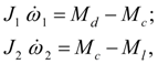
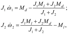
Blocking of frictional clutches and hydraulic torque converters Above (see the section «Introduction» ) it was marked, that feature of transient processes in mechanical and hydro mechanical drives is presence in blocked elements (frictional clutches and blocked hydraulic torque converters) two basic modes: 1) rotation of leading and conducted parts with slipping; 2) rotation of leading and conducted parts without slipping (a blocking mode). The known solution of a problem of simulation of a blocking mode in mechanical drive with one blocked element [1, 5, 7], for a friction clutch, for example, is reduced [5] to a classical problem about dry friction model at zero speed of moving mass [6]. As to simulation drives with many blocked elements (as it takes place, for example, in modern hydro mechanical transmissions of mobile machines) this problem is interfaced to the certain difficulties as conditions of blocking of each blocked element depend on structure of the scheme, distributions of the external moments and the resulted moments of inertia, and also a mode of rotation of other blocked elements entering into the considered of a drive scheme. At simulation of blocking mode of rotating masses of frictional clutches and blocked hydraulic torque converters it is possible to carry out joining of the sites neighboring on these elements, having united them in one site and to make recalculation of the resulted moments of inertia, having passed thus to system of the equations of lower order [1]. So, at the unblocked masses the system of the equations describing dynamics of clutch, looks like:
where
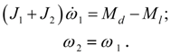
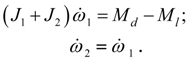
At blocking the system of equations (36) is transformed to a kind:
However, at frequent change of blocking mode and the unblocked condition of clutch at such approach there is a number of the difficulties connected with possible and frequent change of structure of the scheme and the system of differential equations. Differently, the constant control of operating modes of these elements, recalculation of moments of inertia and acceptance of certain actions over change of the simplified scheme is required. It will lead to complication of algorithm of the solution and much greater time of calculations.
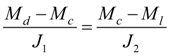
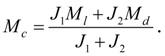
Below the method of forming of the equations is stated, allowing at simulation of dynamics of sites of the scheme irrespective of a condition of blocked masses to keep the constant structure of system of the equations. We’ll show, that transition from the equations of a kind (36) to the equations of a kind (37) is not obligatory as at correct definition of the moment
Conditions of blocking of friction clutches and hydraulic torque converters.
Let,
hence,
Substituting the expression (39) for
whence follows:
Thus, if
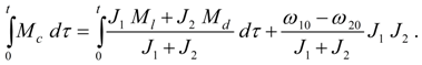
Let's consider equality
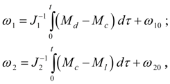
Let's integrate the equations (36) once on
t
and resolve them relatively
where
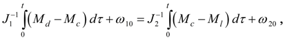
From a condition of equality of speeds
whence follows:
On the other hand, if (44) takes place then its substitution in the system (42) gives
Thus, conditions
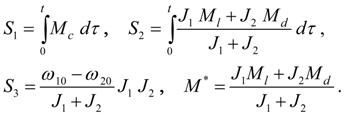
The analysis of blocking conditions of clutches. Let's enter the denotations :
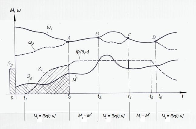
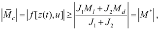
Let the limiting moment developed by clutch
Fig. 6. Geometrical interpretation of clutch blocking mode.
At
therefore there will be a jump of the moment
M
c
with
and
M
c
to within a sign becomes equal to
Blocking conditions (46) – (47) have been considered at record of mathematical models of a friction clutch (15) and a hydraulic torque converter (19) – (20).
For hydraulic torque converter with overtaking clutch always
|
Contents
>> Engineering Mathematics
>> Hydro Mechanical Drives and Transmissions
>> Dynamic Analysis
>> Modeling of blocking mode
>> Blocking of friction clutches and hydraulic torque converters