|
The general case of blocking of arbitrary number of clutches
Let's consider algorithm of definition of the moment
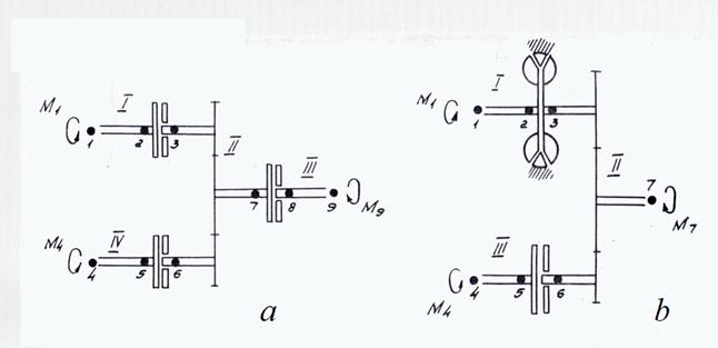
Fig. 7. To a conclusion of the blocking equations
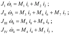
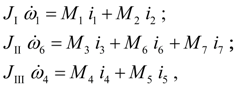
On Fig. 7 fragments of the drive schemes containing blocked elements rigidly connected with each other are presented: 1) parallel-serial connection of three frictional clutches (Fig. 7 а ); 2) parallel connection of hydraulic torque converter and frictional clutch (Fig. 7 b ). Let's consider first of all the scheme on Fig. 7 а . It consists of four sites. The dynamics equations of the scheme sites I – IV look like:
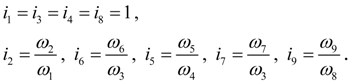
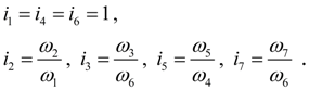
here
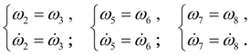
Let in some time moment it has appeared:
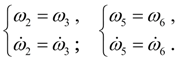
Let's assume, that all three clutches are blocked, then
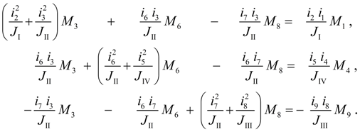
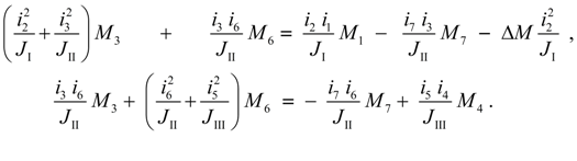
Considering (49), from equations (48) and equality (50) we’ll receive the following system of the equations in unknowns
Although
Solving system of the equations (51), we’ll receive the seeking moments
Now we’ll address to the scheme on Fig. 7 b . It consists of three sites. The dynamics equations of sites I – III look like:
where
Let
Considering (53), from (52) and (54) we’ll receive the following blocking equations:
Solving the equations (55)
relatively
The considered examples allow to pass to formalization of algorithm of drawing up of blocking equations generally.
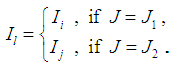
Let's preliminary note the following circumstances following from considered examples. Let some clutch at which
Thus, all diagonal elements of a matrix of coefficients of the blocking equations have the form (56). The unknown moments of others clutches, rigidly connected with the first, can also enter into the same equation. It means, that one of nodes of another clutch (let it will be node n ) enters into the site of the scheme containing either node i , or node j . Then the factor at the unknown moment of this clutch will be equal to:
where
The sign « + » undertakes, if either nodes j and n are included into one site and node n is initial, or units i and n are included into one site and unit n is final (i.e. these clutches are connected in parallel); the sign « – » – otherwise (at consecutive connection of clutches). If the moment in node n is known (it is possible in the two cases: either the unit n is not a node of clutch, or a clutch, containing unit n , is not blocked), then its value increased by coefficient of a kind (57), is transferred to the right part of the equation.
Formally process of drawing up of the blocking equations is reduced generally (at any number of the blocked elements rigidly connected with each other) to the following algorithm. First of all the all clutches which can be blocked, i.e. clutches at which
Tab 2. Information about clutches with possible blocking
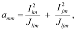
A clutch with number т ( т = 1, ... , N ) is considered. Diagonal elements of a matrix of coefficients of the blocking equations are calculated from the formula:
where
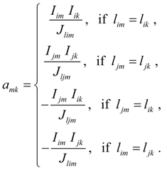
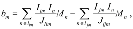
If the m -th clutch is rigidly connected with k -th clutch, then not diagonal element of a matrix of coefficients is equal to:
The right parts of the blocking equations for m -th clutch are calculated in the form of:
where n – external nodes which are not entering into input ( i ) and output ( j ) nodes of clutches which can be blocked (tab. 2)
After detour of all
N
clutches the system of
N
linear blocking equations in
N
unknown moments is generated. Each moment received as a result of the solution of the blocking equations is necessary for checking up, whether it satisfies to blocking conditions of the given clutch. For this purpose it is necessary to substitute its value in corresponding given clutch blocking conditions (15), (19) or (20) instead of
If the all moments satisfy to blocking conditions then process of drawing up and decision of the blocking equations comes to the end. If the moment of any clutch does not satisfy to blocking conditions, then this clutch is excluded from among blocked, and process of drawing up and the solution of the blocking equations repeats again. Thus the moment of not blocked clutch is equal to
|
Contents
>> Engineering Mathematics
>> Hydro Mechanical Drives and Transmissions
>> Dynamic Analysis
>> Modeling of blocking mode
>> General case of blocking of arbitrary number of clutches