Contents
>> Analysis and Design
>> Systems of Hydraulic Drives
>> Hydraulic Transmissions of Single Bucket Excavators
>> Traction-dynamic analysis of hydraulic transmissions of wheel single bucket excavators of III-IV dimension groups
|
Traction-dynamic analysis of volumetric hydraulic transmissions
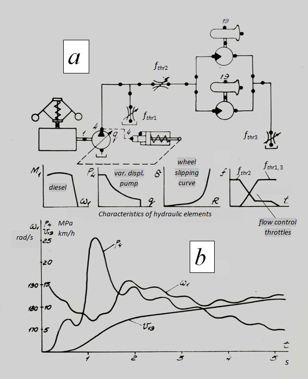
Fig. 1. The rated diagram of volumetric hydraulic transmission of wheel single-bucket excavator of III - IV dimensional groups (Fig. 1, a ) consists of a diesel engine, a variable displacement pump with a power regulator, pipelines, tees, hydraulic motor-wheels and three throttles of variable through passage section. In volumetric hydraulic transmission the bridge diagram is applied, therefore work of two hydraulic motor-wheels of each of bridges in the rated diagram is simulated by one hydraulic motor-wheel with the double mechanical parameters (a moment of inertia, the hydraulic motor geometric volume, factors of mechanical and volumetric losses and so forth). The last is fair at movement of the machine by way of on a straight line when both wheels of the same bridges work at identical influence of a road covering. Other feature is a replacement of directional control valve with the nonlinear characteristic of opening throttling windows, distinct from rong>trapezoidal form, by three throttles THR1, THR1, THR3 of variable through passage section. The law of variation in time of through passage sections of these throttles was specified in program module PERTR (one of subroutines of system HYDRA), modeling external indignations and signals of control. In the same place characteristics of basic elements of a drive (a diesel engine, a power regulator of the hydraulic pump, slipping of wheels) are given.The considered diagram of a hydraulic drive consists of 21 elements, has 30 nodes; the order of solved system of the equations of mathematical model is equal 50. As a result of calculations [1], the dependences describing dynamic processes of dispersal of the machine at takeoff (Fig. 1, b ) have been received. From the resulted oscillograms it is visible, that at inclusion of the hydraulic control valve spool modeled by throttles THR1, THR1, THR3, pressure р 4 in a pressure head chamber of the hydraulic cylinder grows and reaches at t ≈ 1.16 s a maximum equal approximately 26 MPa. At this time angular speed ω 1 of a diesel engine shaft falls with 190 up to 175 is rad/s, and speed of the machine v 19 grows with 0 up to 5 km/h. It occurs that at dispersal of the machine both force of road resistance, and forces of inertia are overcome that is possible only due to high pressure in a pressure piping. Thus a needed moment on the pump shaft increases that leads to an additional load of a diesel engine and as consequence, to reduction of angular speed of its shaft. In the further at achievement of the certain capacity there is an operation of a power regulator which reduces the pump flow. Pressure р 4 thus falls, that leads to growth of ω 1 , as well as to slower dispersal (increasing of v 19 ). At t ≥ 5 s a speed v 19 is stabilized and makes about 12 km/h. On the resulted graphs (Fig. 1, b ) fluctuations of angular speed ω 1 and pressure р 4 with frequency of 1.5...2 Hz are traced also. The set of similar calculations has allowed specifying traction-dynamic characteristics of volumetric hydraulic transmissions of wheel single-bucket excavator of III – IV dimensional groups. |
