Contents
>> Analysis and Design
>> Systems of Hydraulic Drives
>> Hydraulic Drives of Building Self-propelled Cranes
>> Dynamics of hydraulic drives of main winch and mechanism of lifting-lowering of boom of the building self-propelled cranes capacity 25 and 100 tons
|
Dynamics of hydraulic drives of the main winch and the mechanism of lifting-lowering
In conditions of a plenty of models of cranes and a wide range of loads the decision of such problem is essentially facilitated by application of software of the computer-aided analysis. In particular, by means of the program HYDRA researches of dynamics of hydraulic systems of the main rise winch and the mechanism of a boom slope for cranes by carrying capacity 25 and 100 tons have been carried out. These mechanisms in modes of lowering of cargoes, a boom at wrong adjustment of brake and pressure relief valves are subject to self-oscillations. Therefore objective of the executed researches was definition of values of some the parameters providing smooth running of mechanisms in specified modes, as well as an assessment of their influence on stability of work, character of transients in a hydraulic drive, peak pressures.
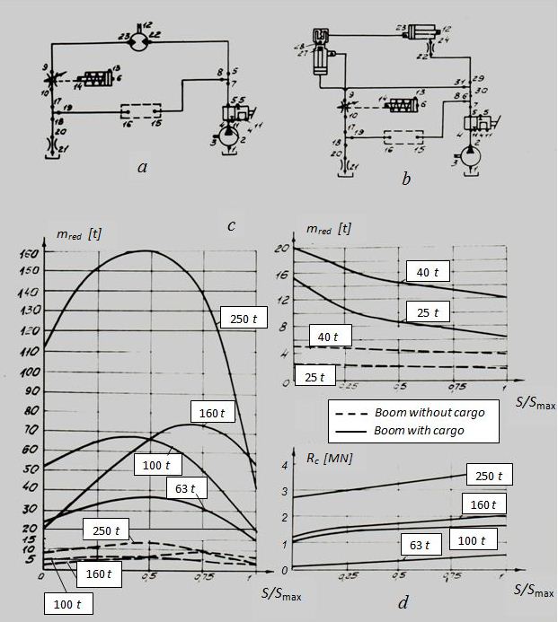
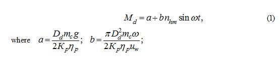
Fig. 1. On Fig. 1, a , b , rated diagrams of hydraulic systems of cranes are resulted: a hydraulic drive of the cargo winch ( a ) and a hydraulic drive of the mechanism of a boom slope ( b ) with the nodes 1, ... , 31 put on them. Each typical hydraulic element (the pump, the hydraulic motor, the valve, etc.) is described by the certain mathematical model reflecting its basic dynamic properties. For the direct operation pressure relief valve connecting nodes 15 and 16, the simplified mathematical model, described only static characteristic has been used within the limits of the considered problem. The brake valve is presented on the rated diagram in the form of a combination of the spring-loaded piston of a regulator and an adjustable throttle which through passage section is function of the piston movement.As the basic revolting influences have been accepted: forces, moments, reduced weights, a movement of the hydraulic control valve spool. Moment on the winch drum shaft in view of a dynamic load [3] is:
Dependences of the boom mass with a cargo m red and forces R c , reduced to a rod of the hydraulic cylinder of the boom lifting-lowering mechanism, of the relative stroke of the piston S / S max where S max – the maximal stroke of the piston, are presented on Fig. 1, c , d . Movement of the hydraulic control valve spool from one position to another was carried out of linear law for 1 s. During modeling hydraulic systems a stability of modes of lowering of the crane mechanisms was checked at various adjustment pressures p b of the brake valve (pressure of the beginning of opening of a stop-adjustable spool) which changed from 2 up to 5 MPa. The dynamic analysis of hydraulic systems of the cargo winch and the boom slope mechanism, for example, for the crane carrying capacity 100 t, was spent at the following values of main parameters: geometric volumes of the pump and two hydraulic motors of 225 cm 3 /rev; diameters of the hydraulic cylinder piston and rod of 300 mm and 200 mm, a stroke of the piston of 2980 mm; diameter and length of pressure and drain pipes according to 32 mm and 2 m; the adjustment pressure of the pressure relief valve p prv = 17.5 MPa; an angular speed of the pump shaft 100 rad/s; the working liquid elasticity volumetric module of 1000 MPa; the maximal area of through passage section of an adjustable throttle 9-10 was equal 2.4 cm 2 ; a nominal bore diameter and a stroke of the hydraulic control valve spool are equal according to 32 mm and 24 mm. In cranes of more carrying capacities the increase of quantity of hydraulic engines was considered by respective alteration of parameters of the hydraulic cylinder or the hydraulic motor. The analysis of the received results has shown that the most sensitive to variation of parameters of adjustment is the mechanism of load-lifting winch. Fluctuations at transients in hydraulic systems of winches for cranes of all considered capacities begin at values p b in 1.5 times greater, than in hydraulic systems of the boom lifting-lowering. Fig. 2, a shows the dependencies [2], with the help of which it is recommended to choose the adjustment pressure of the pressure relief and brake valve for mechanisms of winch and the boom lifting-lowering.
Fig. 2. On Fig. 2, b , c , d the typical rated oscillograms of transients in hydraulic systems of mechanisms of the cargo winch and the boom lifting-lowering for the crane by carrying capacity 100 t in a mode of lowering are resulted at p b = 3.5 MPa.As can be seen from Fig. 2, b stabilization of the boom lowering speed v 12 occurs more quickly (0.7 s), than stabilization of frequency of the hydraulic motor shaft rotation n 12 (1.1 s) which has thus rather amplitude and smaller frequency of fluctuations. Fluctuations of pressures (Fig. 2, c ) in bringing and allocating pipe lines of the hydraulic motor p 22 , p 23 m and the hydraulic cylinder p 24 , p 23 c have identical frequency, but differ on amplitude and a phase. Attenuation of fluctuations of these sizes up to the established values of amplitude in the winch mechanism occurs through 1.1 s after the beginning of switching of a spool. Fluctuations of pressures in the hydraulic cylinder occur with small amplitude and low frequency that testifies to smaller susceptibility of hydraulic system of the boom lifting-lowering mechanism to self-oscillations. Dynamics of movements x 14 m and x 14 c of the brake valve spool at work of winch and the boom slope mechanism in the hydraulic system, as well as the law of movement of the hydraulic control valve spool х are shown on Fig. 2, d . The analysis of oscillograms has shown, that hydraulic systems possess a sufficient degree of damping of elements for clearing own fluctuations. The adjustment pressure of the pressure relief valve p prv , limiting the pressure developed by the pump during lowering of a cargo and a boom has been established, that, does not render influence on stability of these processes. However, for prevention of unjustified losses of energy by the basic condition for a choice of size p prv there should be maintenance of nominal speed of lowering. By calculations it has been established, that lowering of mechanisms begins only at compliance with a condition p prv / p b > 1 as only thus opening the brake valve begins. Achievement of nominal speed of lowering at completely open channel of the hydraulic control valve is probably only at fulfillment of the condition p prv / p b ≥ 1.2. In view of the static characteristic of the pressure relief valve the stock on pressure for maintenance of its stable work together with the brake valve has been accepted. The received rated results have been checked experimentally up at stands, as well as on cranes by carrying capacity 25 and 40 t [3]. The transients received by experiment, have the same character, as rated ones, and their parameters differ no more than on 5-8 % that testifies to a sufficient correctness of the executed numerical analysis. On the basis of the fulfilled researches basic diagrams of hydraulic systems of the cranes have been updated, the level of adjustment pressure of the pressure relief and brake valves is proved and lowered; dynamic characteristics of hydraulic systems are improved. |