|
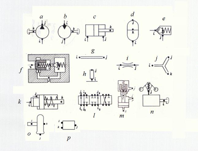
Structure description of arbitrary hydraulic circuits The analysis of the various hydraulic systems applied in various mobile machines (automobiles, road, building, digging-transport machines, excavators, tractors, etc.), shows, that there is a finite set of base hydraulic elements by means of which it is possible to synthesize practically any circuit of hydraulic drive. These elements are: pump, hydraulic motor, hydraulic cylinder, valves of direct and indirect action, throttle (local resistance), pipeline (including, a deadlock site of pipeline or a cavity), tee (divider or adder of flows), power regulator, hydraulic accumulator, pilot operated check valve, directional control valve, diesel engine with a centrifugal regulator, wheel carrier, elements of automatic control systems (ACS). Calculation of any hydraulic circuit is reduced to definition of variable pressures, flows, speeds and positions of mobile parts in points of connection of hydraulic elements – nodes of the circuit. Thus of the same node can be simultaneously an output of one element and an input of another. Any hydraulic circuit can be considered as set of elements making it and nodes – points of connection of these elements. Each element of the hydraulic circuit, except directional control valve, it is possible to present in the form of a three-node element with nodes i (input), j (output) and k (control or transformation of energy), connecting it with other elements of the circuit (Fig. 1).
Fig. 1. Base hydraulic elements and their nodes a – pump, b – hydraulic motor, c – hydraulic cylinder, d – hydraulic accumulator, e – valve of direct action, f – valve of indirect action, g – pipeline, h – deadlock site of pipeline (cavity), i – throttle (local resistance), j – tee, k – power regulator, l – directional control valve, m – pilot operated check valve, n – diesel engine with a centrifugal regulator, o – wheel carrier, p – linear dynamic link of automatic control system (ACS). The input and output of an element are defined by the accepted direction of flow of working liquid. At change of a direction of flow the sign of the corresponding parameters describing work of an element (pressure difference, flow of a liquid, etc.) varies. According to it the following classification of nodes of base hydraulic elements is accepted. Here diesel engine as the most widespread type of drive engine in mobile machines is presented also. Table 1. Classification of base hydraulic elements nodes
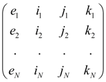
According to the reduced classification each type of element has received a special name – the identifier allowing at forming of the general model of hydraulic system to choose in library of mathematical models of hydraulic elements the necessary group of the equations, namely: mathematical model of the given type element. Following identifiers of base hydraulic elements have been chosen: PUMP (pump), MOTOR (hydraulic motor), CYLINDER (hydraulic cylinder), PIPE (pipeline), VALVE (valve of direct action), etc. According to the entered identification each element e of hydraulic circuit concerns to the certain type with corresponding it nodes i , j , k . Then the structure of any hydraulic circuit after numbering its all nodes is described by the following matrix S :
S
=
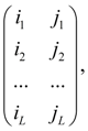
where e 1 , …. , e N – elements of hydraulic circuit, N – their number. The identifier e m defines the mathematical model corresponding an element, and numbers of nodes i m , j m , k m establishments of conditions of communication of elements with each other serve for indexation of variables and, as consequence. For example, if the output of an element e m is at the same time an input of an element e n it is obvious, that j m = i n and therefore, variables on an output e m and on an input e n coincide, i.e. the corresponding condition of communication takes place. As a result of such description of structure of the circuit those equations by which elements entering into the circuit are described will be chosen from the general library of mathematical models of elements, and indexation of variables entering into the equations (a condition of communications), will be established on a basis of numbering nodes of elements specified in matrix S . The unique element which is dropping out of the general concept of a three-node element is directional control valve as the number of nodes adjoining them can be more than three. Therefore we’ll consider directional control valve as set of local resistances – possible connections of nodes of a spool (Fig. 1 l ). Then its structure can be described by forming of additional matrix U :
U =
where i 1 , j 1 , i 2 , j 2 , ... , i L , j L – numbers of nodes of input and output of connections 1, 2, ... , L of directional control valve spool, L – number of connections. Thus, the description of structure (topology) of any hydraulic circuit for carrying out of dynamic analysis is formalized by: - drawings of nodes on simplified circuit – points of connection of elements, and numbering of nodes; - forming of structural matrix S on a basis of identification of base elements and numberings of their nodes in the circuit; - forming of corresponding number of matrices U at presence of directional control valves in the circuit. |
Contents
>> Engineering Mathematics
>> Hydraulic Systems
>> Dynamic Analysis
>> Structure description of hydraulic circuits