|
Forming and solving algorithms of hydraulic circuit math model Forming of input data. All input information for carrying out of dynamic analysis of circuit of hydraulic drive consists of two parts: - information on structure of the considered hydraulic circuit; - information about physical and design data of the hydraulic circuit elements. The first part of the input information is formed according to the method of the structure description of hydraulic circuits stated above, based on classification of base hydraulic elements, introduction of the generalized three-node element with nodes i (input), j (output) and k (control, transformation of energy, supply or taking away of power). On a basis of the entered classification each hydraulic element has received the certain identifier е , designating type of element and unequivocally defining group of equations for mathematical description of the given type element. According to it special forms (tables) of input data have been developed. Each element (except for directional control valves) is described by the line of table of input data having the following structure:
where n – number of element; А – matrix-line of coefficients describing physical, geometrical and design data of the element that makes the maintenance of the second part of the input information. At elements having only two nodes (for example, throttle, pipeline, diesel engine) the third node is designated by zero. Number of element n is intended to choice the necessary array of factors from general field of input data at forming of system of equations. As already it was marked above, the unique element which is dropping out of the concept of a three-node element is a directional control valve as a number of nodes adjoining it can be more than three. Therefore its description differs from other hydraulic elements. After numbering nodes of directional control valve it is necessary to write down in pairs numbers of nodes of its channels in various positions of spool, and the order of following of nodes (input-output) for each channel of spool is defined by direction of flow of working liquid. Thus change of direction of flow at change of position of spool can occur not in whole circuit. For example, in pressure head and drain lines of the directional control valve the direction of flow does not vary. Therefore for account of the direction of flow in node for each connection alongside with number of node it is necessary to specify a sign on flow in this node which is defined by the accepted positive direction of flow in a pipeline adjoining the given node. Each connection of nodes of directional control valve represents local resistance with variable area of through passage section depending on position of spool (Fig. 4). In view of these features the tables for directional control valves with other structure have been developed:
where
е
– the identifier of directional control valve;
n
– number of the directional control valve;
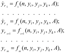
Representation of input data in such kind allows to make the uniform description of the circuit as switching of a spool from one position in another will automatically define the scheme of connections of elements. For forming of mathematical model of hydraulic system dynamics it is necessary to give also parameters of a working liquid entering into the equations ( density , kinematic viscosity , volumetric module of elasticity ). Forming of mathematical model of hydraulic system as a whole. As a result of analysis of line of the table of input data for each element depending on its identifier the system of differential and-or algebraic equations of a kind is formed:
where
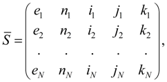
For directional control valves the analysis of connections of its nodes is preceded with forming of the equations, as in intermediate position of a spool (at its switching from one position in another) in one node some connections can be crossed. Therefore flows in nodes belonging simultaneously various connections, turn out summation of flows in corresponding connections [see the equations (22), being analogue of the Kirchhoff’s first law for electric circuits]. The description of each hydraulic element is realized generally by two separate blocks: D (differential equations of mathematical model of element) and-or A (algebraic or transcendental equations of mathematical model of element). On a basis of input information the following fields of input data are formed. Matrix of communications:
differing matrix
S
[see (1)] presence of an additional column
Matrix of parameters of elements of hydraulic system:
where
Forming of mathematical model of hydraulic system is carried out on the following algorithm. The element
External influences and control signals. Control of model (the system of the equations solving) is carried out by the special block which function includes generating signals of external influence: forces of resistance, external loadings in separate elements of hydraulic system (hydraulic motors, hydraulic cylinders), switching of operating hydraulic elements (spools of directional control valves, operated valves, adjustable throttles, pumps, etc.); stop of solving on the given condition, etc. In the control block it is possible to simulate as typical external influences (sine wave, intermittent, linear, etc.), and non-standard, taking place in most cases and defined by a specific problem. Moreover, for consideration of problems with changing physical and design data (variable masses and moments of inertia, pressures of adjustment of valves, etc.) in the control block it is possible to provide the task of these values as function of time or other variable received as a result of solution. Besides in the control block the forming of operating influences and forces of resistance as the functions approximated by a final set of discrete values or having a certain spectrum is obviously possible.
Algorithm of solving.
For integration of systems of the differential equations now there is a huge set of methods of numerical integration (Runge-Kutta, Euler’s, Gear's methods and their updating, etc.), on a basis of which a majority of various corresponding programs has been developed that allows to choose the suitable tool of the solution always.
However, in our case of simulation of dynamics of hydraulic systems there is a feature, consisting that the received system of the equations – the mixed type, alongside with differential it contains also algebraic (transcendental) equations for definition of flows of pumps, hydraulic motors, losses of pressure on length of pipelines, polytropic process in a gas cavity of the hydro pneumatic accumulator, various nonlinearity. The solution of such systems of the equations in the closed form (analytically) is not obviously possible because of insuperable complexities of transformations necessary for it. Therefore for search of the numerical solution it is possible to act as follows. Having values of pressure on input of the pipeline on
n
-th step of integration
i.e. having taken values
In view of small step of numerical integration, and also small all second addendum composed in the right part (43) an error received at such replacement, is negligible small. By virtue of the stated reasons the equation of losses of pressure on length of the pipelines, written down in the form of (43), yields quite satisfactory results and allows to solve other equations (for definition of flows) in a finite kind. |
Contents
>> Engineering Mathematics
>> Hydraulic Systems
>> Dynamic Analysis
>> Forming and solving algorithms of hydraulic circuit mathematical model