|
Dynamic synthesis of hydraulic devices - Planning of hydraulic cylinder piston braking law
Planning of the hydraulic cylinder piston braking law
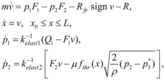
Mathematical model of the considered system looks like:
 (1)
(1)
where
m
– mass of mobile parts of hydraulic cylinder reduced to a rod;
 – areas of pressure head and drain cavities of the hydraulic cylinder;
 – force of dry friction in seals, equal to

 – force of dry friction at absence of pressure;
 – coefficients of proportionality;
R
– external force on a rod;
 – pressures in pressure head and drain cavities of hydraulic cylinder;
 – a piston movement and speed;
 – a piston initial position and a full stroke;
 – coefficients of elasticity of a liquid in cavities of the hydraulic cylinder, equal:

Е
– the reduced volumetric module of elasticity of a working liquid in an elastic environment:

 – a volumetric module of elasticity of a working liquid;
 – diameter and thickness of a wall of the cylinder;
 – an elasticity module of the cylinder wall material;
 – "dead" volumes of cavities of the cylinder;
 a working liquid flow in a pressure head cavity of the cylinder;
 a throttle flow coefficient;
 density of a working liquid;
 pressure behind a throttle;
 through passage section area of throttle as function of piston movement.
The executed from model (1) dynamic calculations of transient processes arising at braking in hydraulic cylinders, in view of their geometry, simplified scheme of loading (impeding or passing), various forms of throttle cracks, reduced masses, etc., had testing character, have shown, that the choice of this or that dependence
 exert
s essential influence on dynamics of brake processes in hydraulic cylinder and consequently should be coordinated as with parameters of a hydraulic drive (reduced to a rod mass and loading, elasticity of hydraulic system, etc.), and with given to braking process requirements (time and braking stroke, peak pressure, etc.)
For the solution of the problem we’ll accept some assumptions:
1) prior to beginning of the piston braking its speed, pressure in cavities of the hydraulic cylinder and a charge of working liquid are constant;
2) considering, that the piston braking occurs on rather small movement, it is possible to consider the reduced mass and force on a rod of the hydraulic cylinder as constants;
3) it is expedient to give such law of the piston movement at braking, at which speed
 strictly decreasing function that allows to accept

Proceeding from it, we’ll plan the law of the piston movement
 during braking
 , having accepted following boundary conditions:
 (2)
(2)
Here
 ,
,
 – a final piston speed;
Т
– braking time.
Let's impose restriction on the maximal pressure
 :
:
 (3)
(3)
whence in view of (1) follows:
 (4)
(4)
where
 – pressure of adjustment of a pressure relief valve of hydraulic system. Let’s consider, that the charge on an input in the hydraulic cylinder changes in conformity with the static characteristic of the valve:
 (5)
(5)
Здесь
 – difference of adjustment and operation pressures of a pressure relief valve.
From (4) follows:
 (6)
(6)
Let's note, that giving as much as possible admissible pressure
 , it is necessary to provide performance of a condition
 as differently the piston braking is impossible.
Having excluded
 from the equations (1), we’ll receive:
 (7)
(7)
At the given law of movement of the piston values
 and
and
 , entering into the formula (7), can be defined either by numerical integration of the third equation of system (1), or analytically as the equation relatively
 is practically
piecewise linear
 In its right part a known function
 is contained, and the charge
 is described by
piecewise linear
dependence (5). Any of these ways provides reception of required dependence
 in the parametrical form:
 (8)
(8)
Having
six
boundary conditions (2), we’ll plan the piston movement law by means of a polynomial of the
fifth
degree:
 (9)
(9)
Whence, differentiating, we’ll receive

Using boundary conditions (2), we come to system of the linear algebraic equations relatively unknown coefficients
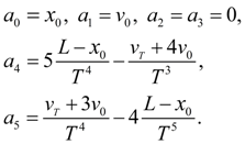
 of the polynomial (9), solving which we’ll receive:
 (10)
(10)
As an initial position of the piston
 is in advance not known, then for its definition, not raising a degree of a polynomial (9), we’ll impose an additional boundary condition:
 (11)
(11)
which in view of (9) and (10) gives:
 (12)
(12)
Then
 (13)
(13)
whence follows, that at
 we have
 i.e. the demanded monotony of
 is provided and
 is reached at
 and is equal:
 (14)
(14)
Then from (6) follows:
 (15)
(15)
whence it is final
 (16)
(16)
Hence, having given the braking time
Т
from a condition (16) and using (12), we’ll receive
 .
.
|


 and is equal:


