|
Structural analysis of hydro mechanical drives Unlike hydraulic systems in mechanical and hydro mechanical transfers connection of elements can be rigid when angular speeds of elements are connected with each other through constant transfer ratios. For such chains of elements it is necessary to carry out reducing of moments of inertia and transfer numbers, uniting rigidly connected elements in one site and describing their by one equation of a kind:
where
J
– the reduced moment of inertia;
The moments and transfer ratios undertake in view of their signs. Boundary elements which divide the drive scheme into sites are elements with separately rotating masses: frictional and hydro dynamical clutches, hydraulic torque converters, wheels, elastic shafts, differentials, i.e. elements with the variable transfer ratio.
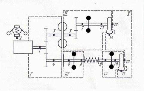
Fig. 2. An example of breakdown of the hydro mechanical transmission scheme on elements, nodes and sites
On Fig. 2 as an example the scheme of the hydro mechanical transmission consisting of a diesel engine (nodes 1, 2), a gear (1, 3, 4), a friction clutch (4, 6), a flywheel (6, 8), an elastic shaft (8, 9), a flywheel (9, 10), a wheel (10, 11, 12), a hydro dynamic clutch (3, 5), a gear (5, 7), a wheel (13, 14, 12), a flywheel (7, 13) is shown.
As a result of the structural analysis the scheme is broken into the following sites (in brackets numbers of nodes of these sites are specified): I (1, 3, 4), II (5, 7, 13), III (6, 8), IV (9, 10), V (14, 11, 12). We’ll note, that the third node at all wheels (in the given example 12) is general (see tab. 1 «Classification of drive base elements nodes» ) as this node is connected with the case of the machine and the machine movement speed "is adhered" to it. The site V corresponds to the machine progressive movement. The centrifugal regulator of a diesel engine is described by the separate equation, therefore the node 2 is not included into the specified sites. All the nodes of the site, are divided on internal and external (for example, on for the site II nodes 5 and 13 – external, and node 7 – internal). All the moments are given or calculated only in external nodes. In turn, external nodes are divided on initial and final ones. Nodes j of the following elements are initial : a diesel engine, a friction clutch, the hydraulic torque converter, a hydro dynamic clutch, a shaft, a wheel, i.e. those elements which are boundary elements of sites. To the boundary elements breaking the scheme on sites, the differential at which nodes i and j belong to differential axes, and node k – to driver belongs also . In case if there is a division of a power stream in differential, nodes i and j are initial nodes of sites; at summation of a power streams nodes i and j – final; the node k to any site does not belong. If the flywheel in node i is not adjoined with other elements the node i a flywheel is initial. If a gear summarizes streams of power, its node k is too initial. Final nodes of sites are nodes i of the same elements (a friction clutch, a hydraulic torque converter, a hydro dynamic clutch, a shaft, a wheel), except for a diesel engine having nodes j and k . Besides nodes j at a flywheel, k at a wheel, j and k at a gear at a branching of a stream of power or only j at summation of streams of power also are final nodes of sites if there are no other elements behind these elements in the scheme. As a site can contain one or several gears, clearly, that such site can have some initial or some final nodes. We’ll agree, that the equations of dynamics of each site of a kind (2) we’ll form in its initial node and if there is some initial nodes – then in its initial node specified first. Presence of several initial nodes of a site complicates algorithm of reducing of moments of inertia and transfer numbers, therefore it is accepted, that if a site has some initial nodes then each of them, since the second, should be simultaneously node k a gear-adder, i.e. a gear in this node adjoins either a shaft, or a driven part of frictional clutch, a hydro dynamic clutch or a hydraulic torque converter. Such condition does not limit a generality of a problem, but considerably simplifies algorithm of reducing of moments of inertia and transfer numbers.
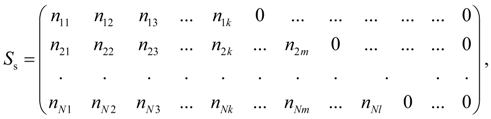
For storage of the information on structure of the scheme the special structural matrix
where 1, 2, …,
N
– numbers of sites;
N
– number of sites;
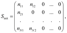
As the site can have branches (at presence of gears) and accordingly some initial and final nodes, it is expedient to have two additional matrixes: matrix of initial nodes
where
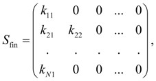
matrix of final nodes
where
Elements of matrixes
After the structural analysis of the scheme ending a number of additional actions is made. In particular, the site "wheel – road", in which some initial nodes (these are points of contact of tires with road) and one final node (the machine progressive moving) is under construction. This site differs from other that the equation of the machine progressive moving is written in final node of a site (the machine speed). Therefore its construction is spent separately, after forming of other sites.
Thus, as a result of the structural analysis of the scheme the following matrices are formed: a matrix
|
Contents
>> Engineering Mathematics
>> Hydro Mechanical Drives and Transmissions
>> Dynamic Analysis
>> Structure description of arbitrary hydro mechanical circuits
>> Structure analysis of hydro mechanical drives