|
Structure description of arbitrary control systems Analysis of control systems applied in various machines, shows, that there is a final set of base elements – dynamic links of automatic control systems (ACS) by means of which it is possible to synthesize practically any control system. Then dynamic analysis of any system is reduced to definition of phase variables (speeds and positions of mobile parts) in points of connection of elements – nodes of circuit. Herewith the same node can be simultaneously an output of one element and an input of another. Thus, any dynamic system, including, and a control system, it is possible to consider as set of elements making it and nodes – points of connection of these elements. Each element is represented in the form of three-node element with nodes i (input), j (output) and k (an additional input or an output), connecting it with other elements in system. The element input and output are defined by the accepted direction of a capacity stream or a control signal. At change of this direction signs on the corresponding parameters describing work of the given element (speed) vary. According to it following classification of nodes of links is accepted. Table 1. Classification of nodes of linear dynamic links of ACS
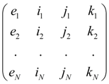
Each type of an element (link of ACS) has received a special name – the identifier allowing at forming of the general model of dynamic system to choose in library of base elements and their mathematical models the necessary group of the equations, namely: model of the given type link of ACS. For link of ACS the identifier LINK is chosen Special table 2 of initial data for the description of linear dynamic links contains the numerical code defining concrete type of a link and a choice of its mathematical model. As well as generally, according to the entered identification each element e of system (in this case, LINK) is related to the certain type with nodes corresponding it: i , j , k . Then the structure of dynamic system after numbering all its nodes is described by the following matrix S :
S
=
where e 1 , …. , e N – elements of system (dynamic links), N – their number. The identifier e m together with a numerical code defines corresponding mathematical model of a link, and numbers of nodes i m , j m , k m serve for indexation of variables and, as consequence, definition of conditions of communication of links with each other. For example, if an output of a link e m is at the same time an input of a link e n , it is obvious, that j m = i n , and therefore, variables on an output e m and on an input e n coincide, i.e. the corresponding condition of communication of these links takes place. As a result of such structure description of system those equations will be chosen from the general library of mathematical models of elements, by which the links entering into system are described, and indexation of the variables entering into the equations (communication conditions), will be established on a basis of numbering nodes of the links specified in matrix S . Thus, the description of structure (topology) of any arbitrary dynamic system is formalized by - drawing on the working scheme of nodes – points of connection of links, and numbering of nodes; - forming of structural matrix S on a basis of identification of links and numbering of their nodes. |
Contents
>> Engineering Mathematics
>> Control Systems
>> Dynamic Analysis of Control System of Hydraulic Drive
>> Structure description of arbitrary control systems