Contents
>> Analysis and Design
>> Systems of Hydraulic Drives
>> Hydraulic Drives of Loaders
>> The analysis of dynamic loads in hydraulic drive of loader ТО-24
|
The analysis of dynamic loads in hydraulic drive of loader ТО-24
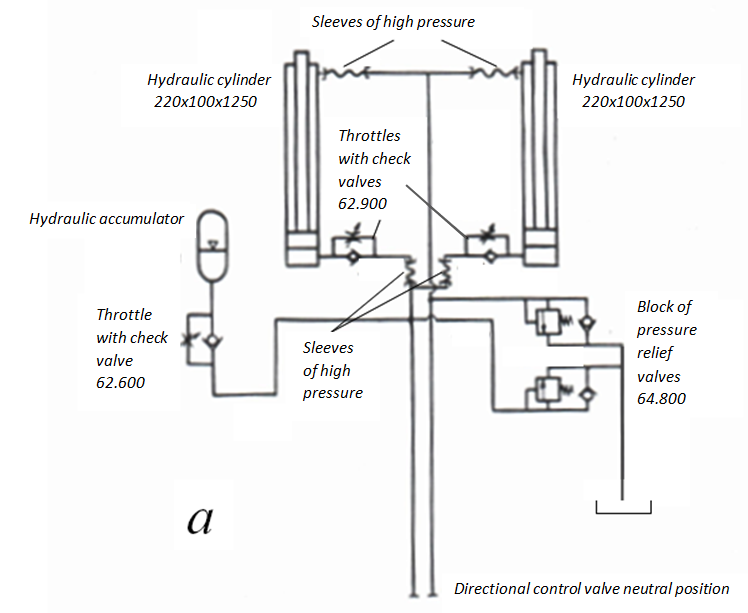
Fig.1 а . The basic circuit of a hydraulic drive of the working equipment of loader ТО-24. It is known, that at executing of working operations, as well as at movement on actual profile road significant dynamic loads can be appeared to machines of the given type. To decrease in peak pressure in hydraulic system and protection of elements of a hydraulic drive, in particular such as sleeves of a high pressure, establish or the hydraulic and pneumatic accumulators which are fulfilling the functions dampers of hydraulic impact, or pressure relief valves. Application of the hydraulic accumulator allows not only to lower peak pressure, but also provides stable position of the working equipment in a transport mode.The developed program HYDRA [1] has been used for an assessment of efficiency and a choice of parameters of the hydraulic accumulator and pressure relief valves. According to the technical project calculations of dynamic loads in hydraulic system of loader ТО-24 in two modes have been lead: a) crossing through an obstacle; b) sharp braking of a ladle with a cargo at lowering (a so-called mode "lowering with picking up"). Input data for dynamic analysis: hydraulic cylinder: the piston diameter 310 mm, the rod diameter 140 mm, the piston stroke 1250 mm, height of cup-type seal 18 mm, force of dry friction at absence of pressure 4.9 kN, the cylinder wall thickness 25 mm, the elasticity module of the cylinder wall material 196200 MPa; pipelines: (9 – 10) and (13 – 11): diameter 34 mm, length 1.1 m, thickness of a wall 10 mm, the elasticity module of a wall material 6475 MPa; other pipelines : diameter 25 mm, thickness of a wall 3 mm (at the pipeline 5 – 4 thickness of a wall is 2.5 mm), length of pipelines: (3 – 15) – 0.5 m, (5 – 4) and (14 – 16) – 1 m, (2 – 1) – 1.5 m, the module of elasticity of a material of a wall 196200 MPa; valves: the check valve (11 – 6 – 12): mass of a mobile part 180 g, rigidity of a spring 2354 N/m, preliminary compression of a spring 16.7 mm, the working area 0.0016 м 2 , an average diameter and factor of expense of throttling slot 45 mm and 0.62, a cone angle of the valve 60 degrees, the maximal stroke of a mobile part of the valve 6 mm, the area of a parallel throttle 0.00101 м 2 ; the check valve (4 – 21 – 19): mass of a mobile part 90 g, rigidity of a spring 1177 N/m, preliminary compression of a spring 16.7 mm, the working area 0.0008 м 2 , an average diameter and factor of expense of throttling slot 32 mm and 0.62, a cone angle of the valve 60 degrees, the maximal stroke of a mobile part of the valve 6 mm, the area of a parallel throttle 0.0005 м 2 ; the pressure relief valve (16 – 17 – 18): mass of a mobile part 116 g, rigidity of a spring 274680 N/m, preliminary compression of a spring 27 mm, the working area 0.000377 м 2 , an average diameter and factor of expense of throttling slot 20 mm and 0.55, a cone angle of the valve 60 degrees, the maximal stroke of a mobile part of the valve 33 mm, the area of a parallel throttle is 0; throttles: (7 – 3) and (10 – 23): the area of through passage section 0.000492 м 2 , a factor of expense 0.62; (24 – 2): the area of through passage section 0.000122 м 2 , a factor of expense 0.62; tees: tees for branching of streams (15 – 13 – 14) and (1 – 3 – 5): diameters 25 mm, factors of local resistance 0.5; hydro pneumatic accumulator: volume 6.3 l, mass of mobile parts 3 kg, the piston diameter 125 mm, the pressure of charged gas 9.81 MPa, exponent of polytropic process 1.4, the piston maximal stroke 450 mm, force of dry friction at absence of pressure 1.962 kN, height of cup-type seal 18 mm, thickness of the cylinder wall 10.5 mm, the elasticity module of a wall material 196200 MPa; as the version the hydro accumulator in volume 16 l (mass of mobile parts of 9 kg, the piston diameter 180 mm, the piston maximal stroke 565 mm, force of dry friction at absence of pressure 2.943 kN, thickness of the cylinder wall 11.5 mm, other parameters are the same that at the accumulator in volume 6.3) was considered; working liquid: density 900 kg/m3, kinematic viscosity 30 cSt, the volumetric elasticity module 1668 MPa.
Dynamics of hydraulic drive of a loader at crossing through an obstacle
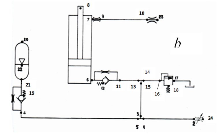
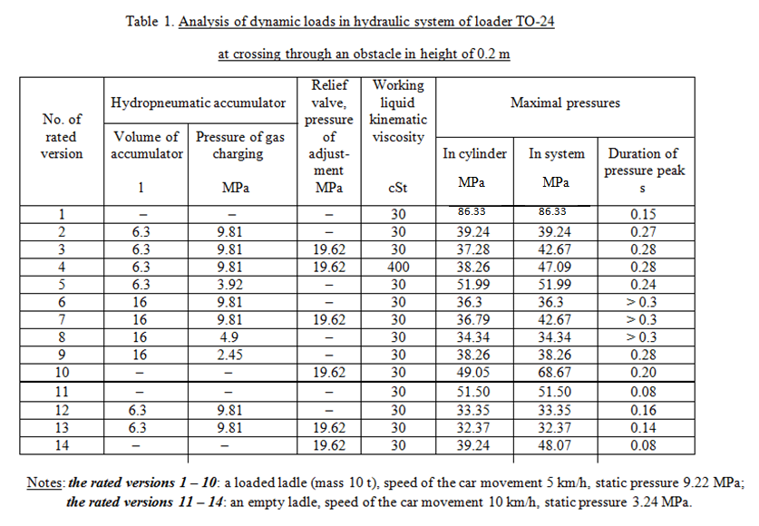
Fig.1 b . The simplified circuit of a hydraulic drive of the working equipment of loader ТО-24. On Fig.1 b the simplified circuit is presented, in which in parallel included hydraulic cylinders (see Fig.1 a ) are replaced by one with the double areas piston and rod cavities. Reduction of parameters of parallel sites of pipelines is executed so that first, to provide appropriating elasticity of cavities with a working liquid, and secondly – equivalence of losses of pressure on length.Trial calculations at crossing a loader through an obstacle have shown extremely high losses of pressure (up to 8 MPa) on length of the pipeline 5 – 4, therefore in the further diameter of this pipeline has been taken equal 25 mm instead of 16 mm, stipulated in the project. In table 1 the considered rated versions 1 – 14 and their primary results are presented, and on Fig.2 – graphs of dynamic processes for some of the specified versions of calculation are presented.
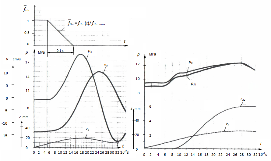
Fig.2. Graphs of dynamic processes in a hydraulic drive of loader ТО-24 at crossing through an obstacle (versions 1-10, tab.1). From graphs and tab.1 it is visible, that availability of the hydro pneumatic accumulator allows to lower peak pressure in the hydraulic system of a loader in 2 – 2.5 times. At the same time pressure relief valves appear much less effective (see a version 10 in tab.1), reducing peak loads only on 20 – 40 %. At the fixed capacity of the hydro accumulator the essential factor influencing dynamics of the hydraulic system is the pressure of charged gas, and this influence the is more, than the capacity of the accumulator is less.The fulfilled calculations have shown that for the given hydraulic system distinction of results for accumulators in capacity 6.3 l and 16 l at pressure of charged gas 9.81 MPa is very insignificant (versions 2 and 6 in tab.1). Thus, on an input of pressure relief valve the peaks of pressure exceeding pressure peaks in the hydraulic cylinder, and characteristic by high frequency of fluctuations (300 – 500 Hz) are observed. However at capacity of the accumulator 6.3 l influence of pressure relief valve affects duration of peak loads (compare Fig. 2 b and 2 c ), and at capacity of the accumulator 16 l the pressure relief valve practically does not influence character of dynamic process. It speaks that at volume of the hydro accumulator 6.3 l rigidity of hydraulic system above and as consequence, peak pressure are longer, that in turn leads to the longer work of the pressure relief valve. For an assessment of influence of viscosity of a working liquid on Fig. 2 d the version 4 with raised on comparison with a version 3 (viscosity of a working liquid 400 cSt vs 30cSt) is presented. Results of versions of calculation 3 and 4 differ a little (compare Fig. 2 c and 2 d ).
Dynamics of hydraulic drive of a loader at lowering a ladle with picking up
Fig.3. Graphs of dynamic processes in hydraulic drive of a loader ТО-24 at lowering a ladle with picking up. Calculations of dynamic loads in a mode of lowering of an arrow of a loader with a loaded ladle with picking up, i.e. lowering at fast overlapping direct control valve (the throttle 2 – 24 is blocked for 0.1 s) have shown insignificant peak pressure of the order 17 – 18 MPa at absence of the hydro accumulator and 12 MPa at availability of the accumulator (Fig.3 a and 3 b ) as the piston speed chosen from a condition of filling of rod cavity in this case is insignificant (~0.14 m/s) and therefore, kinetic energy of the piston in view of the reduced mass is small enough.
Conclusion
Availability of the hydro pneumatic piston accumulator reduces size of pressure peaks in 2 – 2.5 times (from 86 MPa up to 39 – 40 MPa). Thus duration of pressure peak increases twice (from 0.15 s up to 0.3 s). Besides the degree of influence of the pressure relief valve on dynamics of hydraulic system, viscosity of a working liquid that has allowed specifying a choice of the certain parameters of the hydraulic system has been established: the pressure of charged gas, the hydro accumulator volume, etc. |