Contents
>> Analysis and Design
>> Systems of Hydro Mechanical Drives
>> Hydro Mechanical Transmission of Loader
>> Traction-dynamic analysis of hydro mechanical transmission of the loader ТО-21-1
|
Traction-dynamic analysis of hydro mechanical transmission of the loader ТО-21-1
The primary subject of such calculation was research of the transients proceeding in hydro mechanical transmission at takeoff and reversal of the machine. Feature consisted that at modeling transients variation of influence on the lever of control by supply of fuel of the engine was considered.
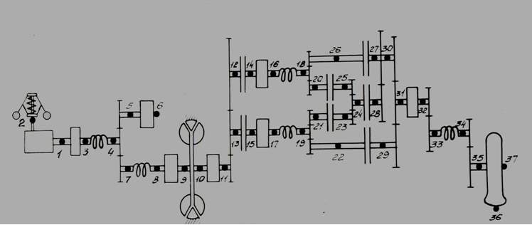
Fig. 1. The rated diagram of hydro mechanical transmission of the loader (Fig. 1) consists of the following elements: the diesel engine with a centrifugal regulator 1-2; gears 4-5-7, 11-12-13, 18-20-26, 19-21-22, 25-24-23, 27-30-28, 30-31-29, 32-33, 34-35; masses of flywheels 1-3, 5-6, 8-9, 10-11, 14-16, 15-17, 31-32; the hydraulic torque converter 9-10; elastic shafts 3-4, 7-8, 16-18, 17-19, 33-34; friction clutches 12-14, 13-15, 20-25, 21-23, 26-27, 24-28, 22-29; a wheel 35-36-37.
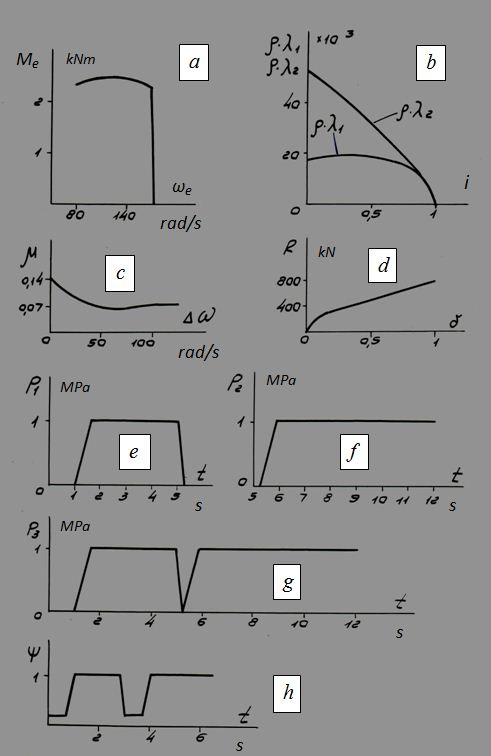
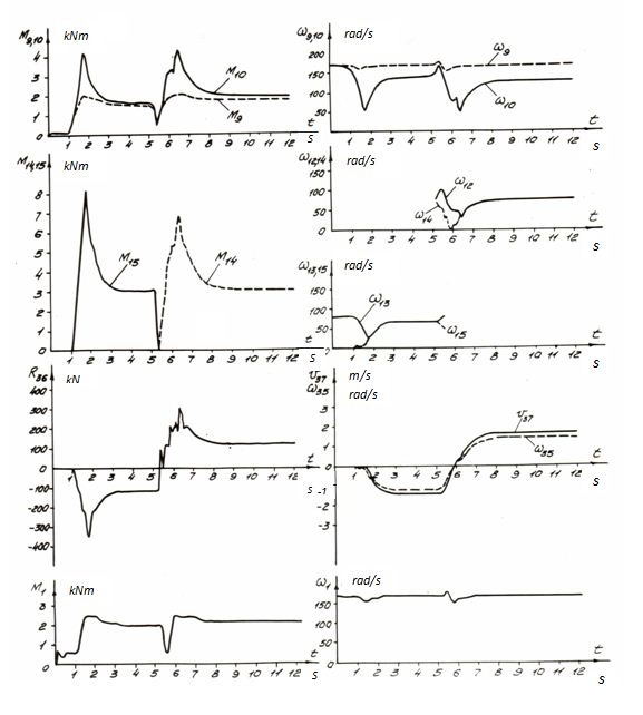
Fig. 2. Characteristics of elements of hydro mechanical transmission (Fig. 2, a–d ): an engine M d ( ω d ), the hydraulic torque converter λ 1, 2 ( i ), friction clutches μ (| Δω |) are certain experimentally, and the characteristic of wheel propelling slipping R ( δ ) is calculated analytically [7].The main parameters of elements of hydro mechanical transmission of the loader: the diesel engine nominal power of 400 kW (at angular speed of the engine shaft 167.52 rad/s); an active diameter of wheels of the hydraulic torque converter of 0.53 m; the tire radius in free state of 1.285 m; mass of the machine of 83000 kg; the movement resistance 117.6 kN (conforms to movement of laden loader on a horizontal site of road with the factor of resistance equal to 0.1). The following the heaviest dynamic stress loading modes were considered: 1) dispersal on I transfer forward (by means of inclusion of friction clutches 13-15 and 22-29) during 3 s; 2) reversal of the loader by switching from I forward transfer to I back (disconnection of the friction clutch 13-15 and inclusion of the friction clutch 12-14 at constantly closed friction clutch 22-29) and dispersal in the opposite direction in nearby 7 s. Friction clutches 20-25 and 21-23 in these cases during all cycle are closed, and friction clutches 24-28 and 26-27 – are opened. On Fig. 2, e – g graphs of signals of control by friction clutches are presented: 1 (nodes 13-15), 2 (nodes 12-14) and 3 (nodes 22-29) – accordingly р 1 ( t ), р 2 ( t ) and р 3 ( t ) – control pressures as functions of time. As results of calculations by means of the program DRIVE transients in hydro mechanical transmission of the loader (Fig. 3) have been received at dispersal and reversal of the machine. Calculations were spent both at a constant fuel supply of the diesel engine, and at influence on it (dumping and increasing of gas thus was simulated). In the latter case relative influence ψ ( t ) on a spring of a diesel engine regulator changed within the limits of from 0.2 up to 1 (Fig. 2, h ).
Fig. 3. The transients have allowed estimating a degree of influence of control of fuel supply in the engine on dynamic loads of hydro mechanical transmission. The following features of course of transients have been noted:– rotating moments on the hydraulic torque converter turbine wheel shaft and shafts of friction clutches accrue according to an increase of pressure of control of friction clutches, and at achievement of a maximum have local decrease because of variation of relative angular speed owing to fluctuations of angular speeds of elastic shaft 16-18 and 17-19 (Fig. 1); – at alignment of angular speeds of leading and conducted disks of friction clutches rotating moments are stabilized and reach the established value at locking of friction clutches; – dynamics of rotating moments of the hydraulic torque converter and friction clutches is characterized in an initial stage by availability of the imposed high-frequency fluctuations because of torsional vibrations of elastic shafts of transmission. Comparison of loading modes of transients with control of fuel supply and without it has allowed to note the following: – dynamic loads at takeoff and reversal of the machine, accompanied influence on the lever of control of fuel supply, decrease in 1.3 – 1.5 times that is caused by decrease in angular speed of a shaft of the engine and an output on a partial regulatory characteristics; – time of slipping of frictional disks during locking at influence on the lever of control of fuel supply decreases in 1.5 times that speaks, first, in lower angular speeds of leading disks of included friction clutches, and secondly, absence of dispersal of leading disks during time of break of a stream of power (at switching transfers). The analysis has shown, that thus in 3.6 times work of slipping of friction clutches that is caused both reduction of time of slipping, and reduction of rotating moments of included friction clutches decreases; – influence on the level of fuel supply control practically does not influence on the period of dispersal of the transmission shafts and the machine as a whole, that speaks smaller time of inclusion due to reduction of angular speeds of friction clutches at decrease of fuel supply and more intensive dispersal of shaft after locking of friction clutches due to the subsequent increase of fuel supply, as well as smaller transfer ratios of the hydraulic torque converter in comparison with process with constant fuel supply. As a result of the fulfilled researches some parameters of the hydro mechanical transmission have been specified, as well as recommendations rather sequence diagram of inclusions of friction clutches (time of overlapping are developed at switching transfers, time of inclusion, etc.). |