Example: solution of the hyperbolic equationDynamics of pressures in the pipeline with a liquid Let's consider dynamic processes in the pipeline with a liquid with an input variable flow Q (t) and an output throttle regulation f (t) (Fig.5).
Fig. 5. The simplified diagram of a pipeline with a liquid After transition in the equations (19) to finite differences we’ll set in a point х 0 the following boundary conditions for a speed u ok :at linear variation of flow 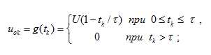 (22)
(22)
at pulsation of flow Boundary conditions for a speed u nk in a point х n look like: 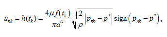 (24)
(24)
where μ – flow coefficient; f ( t ) – the variable area of through passage section of a throttle (Fig.5), similar dependence (22); р* – constant pressure behind a throttle. Let's make the numerical analysis of a liquid dynamics in the pipeline at external influences (22) – (24).
Fig. 6. Dynamics of pressure in input in pipeline at volumetric regulation under the linear law
On Fig.6 the graph of change in time of pressure in input to pipeline in length L = 3 m at change of liquid flow in input under the linear law (22), characteristic for volumetric regulation (for example, pump flow) is presented. At flow variation from maximal U up to zero in time τ = 0.1 s fluctuations of pressure on the first resonant frequency c/ 4 L (in this case ~85 Hz) take place. At a stopping delivery of a liquid during the moment of time t = 0.1 s the amplitude of fluctuations of pressure sharply increases because of jump of an inertial pressure du ok / dt .
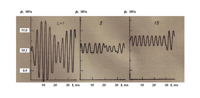
Fig. 7. Dynamics of pressures in input of pipelines at pulsing input flow
On Fig.7 dynamic processes of pressure in input of pipelines in length L = 1, 5 and 15 m are presented. As external influence a pulsing input flow of a liquid Q (t) was given (23), simulating non-uniformity of pump flow with frequency ω ≈ 300 Hz and relative amplitude а = 0.03, close to corresponding parameters of non-uniformity of flow of seven-cylinder axial-piston hydraulic machines. The chosen frequency of influence exceeded the first resonant frequencies of pipelines c/ 4 L , equal accordingly to 255, 51 and 17 Hz. For pipelines in length of 5 and 15 m amplitudes of pressures were equal to 0.2 – 0.4 MPa, and for the pipeline in length of 1 m – approximately in 6 times above as frequency of influence is close to its resonant frequency. In long pipelines in time moments of reflection of direct and return waves occurring with time interval Т = 2 L/c , failures of stationary fluctuations of pressure, accompanied by change of amplitude take place. At calculations of dynamics of the pressure arising at throttle regulation (24) the following values varied: the volumetric module of a liquid elasticity, the pipeline length, the module of a pipe material elasticity, the throttle overlapping time. It is known, that maximal pressure peaks in the pipeline take place in the event that time of a throttle overlapping does not more than time of double run of a wave τ < 2 L/c . (25) The condition (25) was considered as criterion at definition of a range of variation of parameters which numerical values for various versions of calculation are presented in the table.
The fixed values are: the pipe internal diameter d = 30 mm; the liquid density ρ = 901.6 kg/m 3 ; the liquid kinematic viscosity ν = 30 mm 2 /s; a flow coefficient μ = 0.62; the pipe wall thickness δ = 3 mm; F = 5 cm 2 – the maximal area of the throttle through passage section; an integration step Δх = 0.1 m; the given accuracy of an iterative process solution ε = 0.01. In first three versions of calculation of the flow dynamics connected with wave processes, practically it was not observed, as τ >> 2 L/c (for example, for a version 3 we have 2 L/c = 0.03 s < τ = 0.1 s).
Fig. 8. Dynamics of pressures on an input of pipelines at throttle regulation of an output flow by variation of the throttle passage section area under the linear dependence
On Fig.8 graphs of variation of pressure on an input of pipelines for the specified three versions of mathematical model (18) are presented at
throttle regulation of an output flow (24) by variation of the throttle through passage section area
f ( t )
according to the linear
dependence (22).
Fig. 9. Dynamics of wave processes in pipelines with a liquid
Varying various boundary conditions (i.e. a kind of external influences in input and output), geometry and physical parameters of pipelines and
working liquid, it is possible to spend analysis of dynamic processes arising in pipelines of real hydraulic systems for a design stage.
|
Contents
>> Applied Mathematics
>> Numerical Methods
>> Partial Differential Equations
>> Example: solution of the hyperbolic equation