|
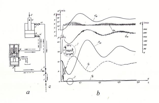
Examples Below a number of examples for an illustration of opportunities of the developed algorithm of simulation of dynamics of hydraulic systems is resulted. In all examples the analysis of transient processes in the chosen circuits of hydraulic drive which can be corrected by a choice of separate parameters of hydraulic elements or change of the initial circuit is spent. 1. Hydraulic systems «pump - hydraulic actuator» Let's consider most often meeting hydraulic circuit including the pump with fixed displacement, a hydraulic actuator (cylinder or motor), necessary connecting pipelines and a pressure relief valve. At all traditional character of the presented hydraulic circuit a number of variants of every possible combinations of parameters is so great, that in practice it is necessary to spend dynamic analysis for each concrete case. On Fig. 6 some characteristic examples of such hydraulic circuits are presented.
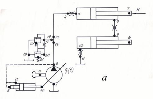
Fig. 6. Examples of characteristic hydraulic circuits and their transient processes.
Specially not citing input constructive data of separate hydraulic elements, we’ll stop on the structure description of the hydraulic circuit according to the form offered above (41) and character of transient processes. The circuit shown on Fig. 6 а , consists of 9 elements connected in 14 nodes. Its structure described by means of a matrix of communications (41), looks like:
For the hydraulic system the following initial conditions are accepted: speed and movement of the hydraulic cylinder piston are equal to zero, angular speed of the pump shaft is constant, all flow from the pump goes into a pipeline 6 – 4. Mathematical model of drive is system of differential-algebraic equations of the 24-th order. The solution of the system of equations is a set of values of pressures, flows of a liquid, speeds and movements in all nodes of hydraulic system as function of time. On Fig. 6 а it is shown, that in initial time moment a peak of pressure р 12 takes place in a piston cavity of the hydraulic cylinder which exceeds pressure of adjustment of a pressure relief valve then insignificant fluctuations of pressure concerning a level of adjustment of a pressure relief valve begin. Thus there is a racing of the hydraulic cylinder piston (speed of the piston v 1 increases). Fluctuation of pressure р 12 is consequence of operation of the valve and fluctuation of its shutter z 11 . In process of the piston racing, since the time moment A , pressure р 12 in a piston cavity of the cylinder starts to fall, but the piston still moves by inertia. Thus the valve already is completely closed. Fluctuations of pressure р 12 and speeds v 1 depends on a combination of parameters of the system. The transient process duration is nearby 0.3 s. On Fig. 6 b the similar circuit is shown, but instead of the hydraulic cylinder the hydraulic motor is used. There are 7 elements and 12 nodes in the circuit, it is described by system mixed differential- algebraic equations of the 20-th order. Initial conditions: angular speed and a turn angle of the hydraulic motor shaft of are equal to zero; angular speed of the pump shaft is constant. At the initial time moment a sharp peak of pressure р 11 takes place which exceeds pressure of adjustment of a pressure relief valve; thus the valve works ( z 1 ) and the hydraulic motor shaft, which moment of inertia is insignificant, is raised. Due to initial peak of pressure angular speed of the hydraulic motor shaft is above its established value. As a result pressure falls, that leads to reduction of the hydraulic motor angular shaft speed. Further in system insignificant fluctuations of angular speed and pressure are observed. Duration of the considered transient process is nearby 0.1 s. On Fig. 6 c the circuit of a hydraulic drive with the pump working on two in parallel connected hydraulic cylinders is presented. The number of elements is equal 7, number of nodes – 12. The mathematical model of hydraulic system consists from 20 algebraic and differential equations. On oscillograms Fig. 6 c transient processes are shown at identical ( I ) both various ( II ) loadings and sizes of hydraulic cylinders. Initial conditions: speeds and movements of pistons are equal to zero; angular speed of the pump shaft is constant. In the symmetric circuit (oscillogram I ) in the initial time moment there is a sharp jump of pressure р 6,10 . In process of increase in pressure raising of pistons of hydraulic cylinders (speed v 8,12 ) begins, then there is a falling pressure р 6,10 up to zero to reduction of speeds of movement and the following output by the established values. Practically transient process in this case is close to shown on Fig. 6 а , but differs pressure of adjustment of pressure relief valve. However at different loadings and sizes of hydraulic cylinders character of transient processes changes (see oscillogram II ). The hydraulic cylinder piston with smaller loading more quickly moves. And besides, upon termination of transient process the hydraulic cylinder piston with greater loading stops, while the hydraulic cylinder piston with smaller loading continues to move with the speed corresponding the pump flow. For this case force acting on the cylinder rod in node 12, is less than the force enclosed to a rod of other cylinder in node 8. Therefore speed v 12 is more than speed v 8 , and v 12 tends to the established value defined by the pump flow whereas v 8 tends to zero. Pressures in piston cavities of cylinders to within losses of pressure in a tee are identical. Duration of transient process is approximately 0.1 s. On Fig. 6 d the circuit of a hydraulic drive in which the pump works on two in parallel connected hydraulic motors is shown. The circuit consists of 7 elements and 12 units and is described by system of the algebraic-differential equations of the 20-th order. As loadings on hydraulic motors shafts are identical, transient process is similar to the circuit with symmetric loadings on hydraulic cylinders. Time of transient process is 0.1 s. At last, on Fig. 6 e the circuit in which the pump works on two consistently connected hydraulic cylinders is shown. There are 8 elements and 13 nodes in the circuit. It is described by system of the differential-algebraic equations of the 21-st order. The transient process is fixed on the oscillogram, corresponds to zero initial values of speeds v 10 , v 13 and movements z 10 , z 13 of hydraulic cylinders pistons at constant angular speed of the pump shaft. Feature of the circuit is that rod cavity of hydraulic cylinder I is connected to a piston cavity of the hydraulic cylinder II , therefore pressure р 3 is more than pressure р 11 . Redistribution of flows Q 3 and Q 11 , and also speeds v 10 and v 13 is defined by a combination of parameters of system as a whole. 2. System «diesel engine - pump - loading» In the examples considered above an angular speed of the pump shaft was accepted by a constant. In real hydraulic systems where as the primary engine the internal combustion engine is often used, with increase of loading (pressure in hydraulic system) angular speed of a shaft of the engine (hence, and the pump) decreases. If in the examples considered above to consider also this factor a character of transient processes can become complicated considerably.
Fig. 7. An example of simulation of dynamics of hydraulic system with diesel engine a – simplified circuit, b – change of the engine shaft moment in function of time and angular speed of a shaft, c – the same at various values of coefficient of viscous friction of centrifugal regulator Let's consider a following example (Fig. 7). The diesel engine with a centrifugal regulator drives the fixed displacement pump on which output the throttle simulating loading in hydraulic system is established. The structure of the circuit (fig. 7а) is described by the following matrix of communications:
The number of the circuit elements is equal 4, number of nodes – 6. The order of the solved mixed system of the differential-algebraic equations – 9. On Fig. 7 b the external static characteristic of a diesel engine with the imposed on it phase diagram of change of the moment versus angular speed of the engine shaft for two values of pressure р 6 of adjustment of a throttle is resulted: 4.8 MPa and 9.2 MPa. From Fig. 7 b it is visible, that a range of angular speed change according to the static characteristic Δω st for M = 153 N·m makes Δω st1 = 5 is rad/s, and for M = 258 N·m Δω st2 = 8 is rad/s. Corresponding ranges of angular speed change on a dynamic characteristic Δω dyn make: Δω dyn1 = 10 rad/s and Δω dyn2 = 17 rad/s. Thus there are also significant changes of the diesel engine loading moment. The specified dynamic characteristics of diesel engine essentially depend on parameters of centrifugal regulator. So on Fig. 7 c it is shown, that at change of coefficient of viscous friction ν from 4400 N·s/m (curve 1 ) up to 7350 N·s/m (curve 2 ) Δω dyn decreases for 30 %. The resulted example shows, that the assumption about constancy of angular speed of the pump shaft in real conditions can appear rather disputable.
3. Dynamics of pilot operated check valve at lowering hydraulic cylinder piston
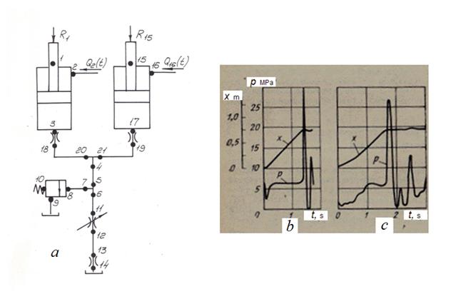
Fig. 8. Dynamics of pilot operated check valve at lowering hydraulic cylinder piston a – simplified circuit, b – transient processes Let's consider as an example the circuit of a hydraulic drive (Fig. 8 а ), including the hydraulic cylinder (nodes 13-11-12), pipelines (9-14, 10-3, 5-4, 2-1), tee (3-4-2), local resistance (14-13 and 11-10) and pilot operated check valve consisting of the check valve (6-9-8) and pusher (6-5-7). Continuous arrows on the circuit note a positive direction of flows in a mode of the hydraulic cylinder piston rise. In this case pilot operated check valve works as usual check valve. By dotted arrows the negative direction of flows (a mode of lowering of the piston) is shown, thus pressure from basic pipeline 1-2 moves simultaneously in a rod cavity of hydraulic cylinder and under the piston of pusher (node 5), which raises the valve, providing the pass of liquid from the hydraulic cylinder and by that – lowering of the hydraulic cylinder piston. Into the hydraulic system (node 1) the negative flow Q = –200 l/min (according to the accepted direction of flows) moves. The hydraulic circuit contains 9 elements and 14 nodes and is described by system of differential-algebraic equations of the 31-st order. Main parameters of the hydraulic system: hydraulic cylinder: piston diameter 100 mm, rod diameter 50 mm, piston stroke 1000 mm, mass reduced to rod 8000 kg, weight of working equipment reduced to rod ~ 80 000 N; pipelines: internal diameter 20 mm, lengths of pipelines: (2-1) – 2m, (10-3) – 2m, (5-4) – 1m, (9-14) – 1m; pilot operated check valve: pusher mass 0.3 kg, valve mass 0.1 kg, pusher operating area 15.9 cm², valve operating area 5.3 cm², pusher stroke 11 mm, initial clearance between pusher and valve 6 mm, coefficient of viscous friction of valve 300 N·s/m, valve spring rigidity 5200 N/m, valve saddle diameter 26 mm, valve cone angle 70º, flow coefficient 0.62; throttle (13-14): conditional pass diameter 7 mm, flow coefficient 0.62; working liquid: density 900 kg/m³, kinematic viscosity 3·10 -5 m²/s, volumetric module of elasticity 5·10 8 N/m². On Fig. 8 b transient processes in considered hydraulic system in a mode of lowering the hydraulic cylinder piston are presented. In initial time moment the system is in balance, and the effort to a rod 80 000 N is counterbalanced by static pressure in a piston cavity 10.4 MPa. At submission into the hydraulic system of flow of a liquid of 200 l/min pressures in a rod cavity of the hydraulic cylinder and simultaneously under the pusher piston р 5 begin to increase. At t ≈ 0.006 s when р 5 reaches value 3.5 MPa, thus р 5 ≈ 0.33 р 9 , the valve of the pilot operated check valve ( z 8 changes from 0 up to 5 mm) opens, pressure of a liquid in a cavity before valve р 9 falls, and pressure in a rod cavity by virtue of inertia of the reduced mass of the hydraulic cylinder continues to grow (speed v 12 in this period of time is small). Pressure р 5 jump up to 12.6 MPa and pressure р 13 drop up to 3.5 MPa are as result observed. In process of the hydraulic cylinder piston raising pressure р 5 decreases, and р 13 increases, there are fading fluctuations of pressure р 5 and р 13 and the hydraulic cylinder piston speed v 12 with frequency about 6 Hz in the system. High-frequency fluctuations of the valve of the pilot operated check valve with frequency of 250...500 Hz and amplitude of 0.5...2 mm caused rebounds of the valve from a pusher, reached emphasis, and their subsequent impacts at the same time take place. However some appreciable influence on target parameters of hydraulic system (pressure р 13 in a piston cavity of the hydraulic cylinder, the pistonmoving speed v 12 ) dynamics of the pilot operated check valve does not render. Nevertheless it is necessary to emphasize, that for achievement of a steady operating mode of the pilot operated check valve and hydraulic system as a whole it is necessary to choose correctly through passage section area of element 13-14. Otherwise, as has shown the analysis of the same circuit, the system becomes unstable. For example, at diameter of a throttle 13-14 equal of 20 mm, there is the significant dynamics, accompanied hydraulic impacts in the system. Therefore for realization of a smooth mode of lowering of the piston in a wide range of loadings in hydraulic systems alongside with the pilot operated check valve usually establish the brake valve providing regulation of speed of lowering of working bodies in function of loading. 4. Hydraulic drive of lowering of hydraulic excavator arrow At lowering an arrow of hydraulic excavator with sharp braking («pickup») there are the high peak pressure, being consequence of hydraulic impact in hydraulic system. For a correct choice of a pressure relief valve carrying out of dynamic analysis of hydraulic system is necessary [9]. We’ll consider the circuit of a hydraulic drive of lowering of an arrow of excavator, resulted on Fig. 9 а . The circuit contains 15 elements and 21 nodes and is described by system of nonlinear algebraic- differential equations of the 38-th order.
Fig. 9. Dynamics of hydraulic system of excavator at sharp braking of arrow a – simplified circuit, b – results of analysis, c – experimental data
Lowering of hydraulic excavator arrow is made by two identical hydraulic cylinders which drain pipelines are united in node 4 in the general drain line. Braking of an arrow is carried out by overlapping of a spool (throttle 11-12). Flows of a working liquid from pump are shown on the circuit as time-dependent flows Q 2 and Q 16 .
At raising of hydraulic cylinders pistons in the beginning of lowering values
Q
2
and
Q
16
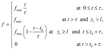
accrue from zero up to the established value corresponding the pump flow, and at braking flow of a liquid in hydraulic cylinders stops. Thus, the area
Here:
f
is
Basic parameters of the hydraulic system: hydraulic cylinders: piston diameter 125 mm, rod diameter 80 mm, piston stroke 1000 mm, mass reduced to rod 17 660 kg, weight of working equipment reduced to rod ~ 76 500 N, pipelines: internal diameter 25 mm, lengths of pipelines: (4-5) - 0.8 m, (6-11) - 0.2 m, (7-8) - 0.2 m, (12-13) - 2.5 m, (18-20) - 2.8 m, (19-21) - 2.8 m, pressure relief valve (4 variants ):
valve cone angle 60º, flow coefficient 0.62; tees: diameters in nodes of tees: 25 mm, 25 mm, 25 mm; coefficients of local resistance of branches of tees: (5-6-7) - 0.2, 1.0, 1.0; (20-21-4) - 2.5, 2.5, 2.5; throttles: area of through passage section of throttles: (3-18) - 4.9 cm², (11-12) - 4.9 cm² (maximal), (13-14) - 2.44 cm², (17-19) - 4.9 cm², flow coefficient 0.62; working liquid: density 900 kg/m³, kinematic viscosity 2·10 -5 m²/s, volumetric module of elasticity (2 variants) 4.9·10 8 N/m² and 9.8·10 8 N/m². On Fig. 9 b , c estimates and experimental dependences of transient processes in hydraulic system of a excavator are presented for comparison at lowering an arrow with «pickup» (sharp braking) at pressure of adjustment of pressure relief valve 30 MPa. Estimate value of peak pressure in a piston cavity of the hydraulic cylinder of rise-lowering of an arrow has made 28.6 MPa and differs from value 26 MPa, received in experiment, on 10 %. As a whole, apparently from oscillograms, character of estimate dependences of pressure р and movement х of hydraulic cylinder rod (Fig. 9 b ), is close to received by experimental way (Fig. 9 c ). Duration of transient processes is 0.1...0.15 s. 5. Main hydraulic drive of automobile concrete pump
Fig. 10 а . Simplified circuit of main hydraulic drive of automobile concrete pump
On Fig. 10 а the simplified circuit of main hydraulic drive of automobile concrete pump is presented. As one cycle of work of hydraulic cylinders of main hydraulic drive is considered only, such elements as valves and directional control valves switching of hydraulic cylinders from suction tact to injection tact of a concrete mix are not included in the simplified circuit. Thus, the simplified circuit of main hydraulic drive of automobile concrete pump consists of 12 elements connected in 21 nodes, and is described by the mixed system of differential and transcendental equations of the 36-th order. Basic parameters of the hydraulic system: pump: 207.32 power regulator: 400.32 power ~51.5 kW, pressure of operation ~13 MPa, hydraulic cylinders: piston diameter 100 mm, rod diameter 63 mm, piston stroke 1400 mm, pressure relief valve: 510.32 (non direct action) pressure of adjustment ~20.6 MPa, pipelines: steel pipe (2-14): diameter 40 mm, length 1.2 m, sleeve of high pressure (15-4): diameter 32 mm, length 1.65 m, steel pipe (16-17): diameter 20 mm, length 1.0 m, throttles : (4-5): area of through passage section 12.56 cm², flow coefficient 0.62, (10-11): area of through passage section 12.56 cm², flow coefficient 0.62, (6-8): area of through passage section 8.04 cm², flow coefficient 0.62, tee (14-15-16): diameters in nodes of tee: 40 mm, 32 mm, 20 mm, coefficients of local resistance of branches of tees: 2.5, 2.5, 2.5; working liquid: density 900 kg/m³, kinematic viscosity 3·10 -5 m²/s, volumetric module of elasticity 9.8·10 8 N/m².
Fig. 10 b. Dynamics of main hydraulic drive of automobile concrete pump
Loading from a column of the concrete mix, acting on the concrete mix cylinders pistons, rigidly connected by the general rods with pistons of hydraulic cylinders, was given by two components: variable force as function of the hydraulic cylinder piston movement z 7 , simulating process of compression of mix in view of incomplete filling of concrete mix cylinders, and process of its moving with the certain resistance (this dependence graph R ( z 7 ) is presented on Fig. 10 b ), and variable mass m ( z 7 ), reduced to the hydraulic cylinder rod (Fig. 10 b ), equal to sum of masses of the hydraulic cylinder piston and rod and the concrete mix cylinder piston on an initial piece of moving ( z 7 ≤ 0.35 m, Fig. 10 b ) and undergoing jump at z 7 = 0.35 m in view of addition of mass of column of concrete mix. Clearly, that such model of loading does not consider possible fluctuations of pressure in a concrete mix. However, the account of this component is a subject of special researches and becomes possible only after carrying out of corresponding experiments with the purpose of studying of character of wave and oscillatory processes in concrete pipe. For simulation of emergency operation of sharp braking of the hydraulic cylinder rod in view of sharp increase of loading (with the purpose of studying of dynamics of hydraulic system at operation of a pressure relief valve) the case of jump of loading has been in addition considered at z 7 > 0.7 м m (see graph R ( z 7 ) on Fig. 10 b ) up to a level maximal loading. As a result of dynamic calculation transient processes of pressure р 5 in a piston cavity of the hydraulic cylinder (5-6-7), speed v 7 and movement z 7 of this hydraulic cylinder rod and to other phase variables of the hydraulic system in function of time t have been received. Smooth enough change of pressure р 5 is characteristic, despite of jump of the reduced mass which has affected only own frequency of the fluctuations, changed with 30 Hz up to 11.4 Hz. The mode of the maximal loadings has been considered both at the disconnected power regulator, and at its connection in the circuit. At sharp increase of loading R with 68.6 kN up to 343 kN and consequently, and pressure р 5 , alongside with a pressure relief valve also power regulator are worked, reducing the pump working geometric volume on ~39 % of its maximal value. However, as the analysis has shown, it has not rendered essential influence on dynamics of drive. Presence of power regulator has affected only decrease in average value of pressure р 5 approximately on 0.7 MPa. |