|
Dynamic express-analysis of hydraulic systems - Library of math models of functional blocks
Library of mathematical models of functional blocks
The mathematical models of functional blocks resulted here are received, proceeding from following assumptions:
- description of hydraulic elements having high own frequencies (valves of various types), is made only at a level of their static characteristics;
- analysis of working liquid flow modes (laminar or turbulent) for definition of coefficients of hydraulic resistance of pipes is not made; losses of pressure on length are considered from formulas of square-law resistance at the fixed (given) values of the reduced coefficients of hydraulic resistance of pipes;
- reducing of elasticity module for cavity with a working liquid in view of elastic properties of walls is not made, this value is given among input data for each functional block of the hydraulic system.
These assumptions define basically a degree of simplification of mathematical models for dynamic express analysis in comparison with more exact mathematical description of hydraulic elements resulted above in the section «
Dynamic analysis of hydraulic systems
» [1 - 3].
Diesel engine with a centrifugal regulator.
For the description of dynamics of diesel engine with a centrifugal regulator (Fig. 1
а
) is enough to write down the equation of shaft moments (node
k
) and the equation of a regulator muff movement (node
l
):
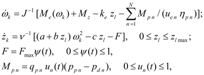 (1)
(1)
where
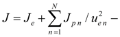 reduced moment of inertia developing own moment of inertia of rotating parts of a diesel engine
 and moments of inertia of pumps
 ;
;
 – transfer number of gear between a diesel engine and the
n
-th pump and mechanical efficiency of the
n
-th pump;
– transfer number of gear between a diesel engine and the
n
-th pump and mechanical efficiency of the
n
-th pump;
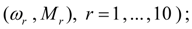
 – characteristic of a diesel engine (dependence of the torque moment
 at the minimal fuel feed from angular speed
 of a shaft in node
k
, approximated by a finite set of points
of a shaft in node
k
, approximated by a finite set of points
 – increment of torque moment at the maximal fuel feed;
 – constant adjustments of diesel engine centrifugal regulator;
 – coefficient of viscous friction;
с
,
F
– rigidity and force of preliminary compression of a regulator spring ,
– coefficient of viscous friction;
с
,
F
– rigidity and force of preliminary compression of a regulator spring ,
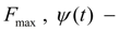 maximal force of preliminary compression of a spring and parameter of its regulation (
 );
);
 – current and maximal movement of a regulator muff;
 – loading moment of engine from the
n
-th pump,
– loading moment of engine from the
n
-th pump,
 parameters of the
n
-th pump :
parameters of the
n
-th pump :
 maximal geometric volume of the
n
-th pump;
maximal geometric volume of the
n
-th pump;
 – control parameter (
 ),
),
 pressures in pressure head and drain lines of the
n
-th pump.
pressures in pressure head and drain lines of the
n
-th pump.
Pump station with opened flow circulation.
According to the simplified circuit (Fig. 2) and the assumptions accepted above the mathematical model of pump station with opened flow circulation can be written down in the form of:
Fig. 2. Simplified circuit of pump station with opened flow circulation.

where
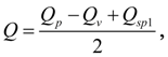

In the equations (2) describing dynamics of pump station with opened flow circulation it is designated:
 pump flow;
 the pump maximal geometric volume;
 control parameter of the pump flow
 ;
;
 angular speed of a diesel engine shaft;
 transfer number of gear between an engine and a pump;
 coefficient of leaks (volumetric losses) of the pump;
 pressure upon an outlet of the pump;
р
* – pressure of operation of a pressure relief valve;
pressure upon an outlet of the pump;
р
* – pressure of operation of a pressure relief valve;
 pressure relief valve flow;
α
– angular coefficient of the valve static characteristic
pressure relief valve flow;
α
– angular coefficient of the valve static characteristic
 reduced module of elasticity and volume of cavities with working liquid;
 flows of liquid in pressure head and drain hydraulic lines of directional control valve;
 flows of liquid in channels of directional control valve;
μ
– flow coefficient of channels of directional control valve;
flows of liquid in channels of directional control valve;
μ
– flow coefficient of channels of directional control valve;
 atmospheric pressure;
 areas of through passage sections of directional control valve channels as function of spool position;
ρ
– density of working liquid;
areas of through passage sections of directional control valve channels as function of spool position;
ρ
– density of working liquid;
 pressure in the beginning of a drain line of directional control valve;
 pressures in pipelines outside of directional control valve ( nodes
i
and
j
) ;
pressures in pipelines outside of directional control valve ( nodes
i
and
j
) ;
 reduced coefficients of pressure losses in view of hydraulic resistance and geometry of pipelines;
 pressure in tank;
 flows in nodes
i
and
j
;
В
– parameter considering inertia effects of throttle cracks of the directional control valve [1].
flows in nodes
i
and
j
;
В
– parameter considering inertia effects of throttle cracks of the directional control valve [1].
Pump station with closed flow circulation.
According to the simplified circuit of pump station with closed flow circulation (Fig. 3) and to assumptions accepted above the mathematical model of pump station of this type looks like:
Fig. 3. Simplified circuit of pump station with closed flow circulation.
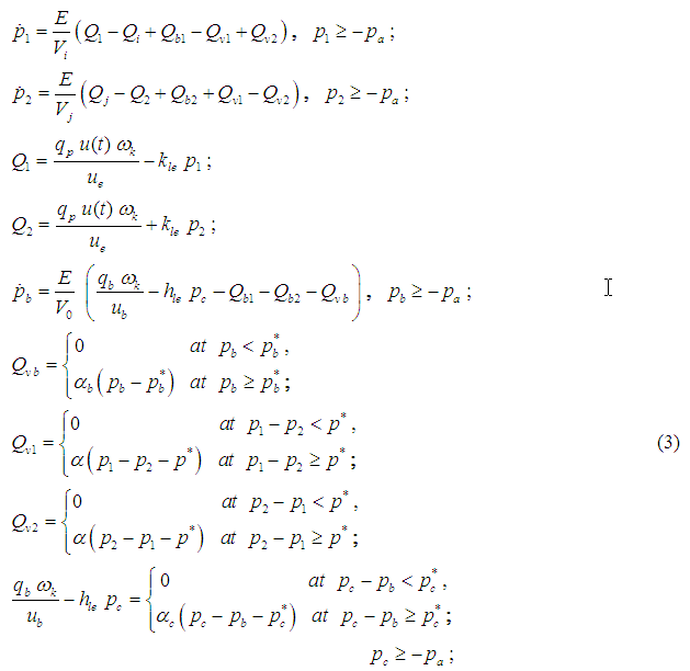
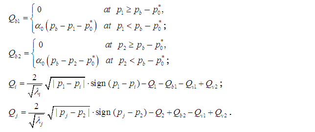
In the equations (3) the following designations are accepted:
 pressures and flows on an outlet and an inlet of basic pump accordingly (Fig. 3);
Е
– reduced module of elasticity of cavities with working liquid;
pressures and flows on an outlet and an inlet of basic pump accordingly (Fig. 3);
Е
– reduced module of elasticity of cavities with working liquid;
 volumes of cavities;
 flows in nodes
i
and
j
;
flows in nodes
i
and
j
;
 boost flows through check valves;
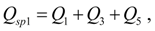
 flows through pressure relief valves;
 the basic pump maximal geometric volume;
 control parameter of the basic pump flow
 ;
;
 angular speed of a diesel engine shaft;
 transfer number of gear between an engine and the basic pump;
 coefficients of leaks (volumetric losses) in the basic pump and the boost pump;
 pressure in a boost system in front of check valves;
 volume of cavity between valves in a boost system;
 the boost pump geometric volume;
 transfer number of gear between an engine and the boost pump;
 control pressure (an outlet of the boost pump);
 flow through the pressure relief valve of the boost;
 angular coefficients of static characteristics of pressure relief valves of basic counter and boost system;
 pressures of operation of pressure relief valves of basic counter and boost system;
 angular coefficient of static characteristic and pressure of operation of pressure control valve;
 angular coefficient of static characteristic and pressure of operation of check valve;
 reduced coefficients of pressure losses on length in view of hydraulic resistance and geometry of pipelines.
Hydraulic motor.
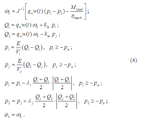
Dynamics of the hydraulic motor with attached pressure head and drain pipelines (the simplified circuit – on Fig. 4) in view of accepted above assumptions can be described by the following system of differential and algebraic equations:
Fig. 4. Simplified circuit of hydraulic motor.
Two in parallel connected hydraulic motors.
The simplified circuit of two in parallel connected hydraulic motors is presented on Fig. 5, and the mathematical model in view of the accepted assumptions looks like:
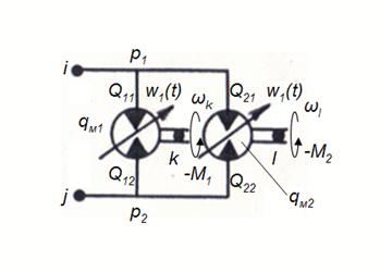
Fig. 5. Simplified circuit of two in parallel connected hydraulic motors.
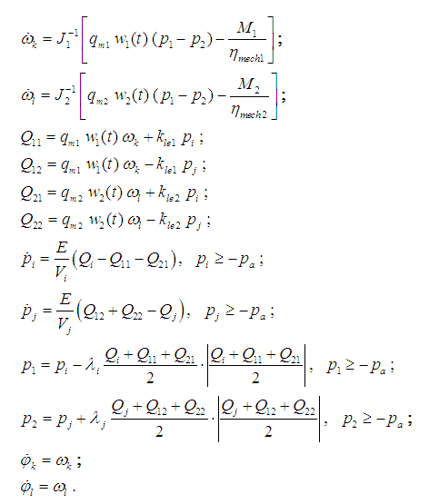 (5)
(5)
In the equations (4) and (5) there are designated:
 reduced to shafts of hydraulic motors moments of inertia of rotating parts;
 maximal geometric volumes of hydraulic motors;
 control parameters of geometric volumes
 ;
;
 pressures upon an inlet and an outlet of hydraulic motors;
 flows on an inlet and an outlet of hydraulic motors;
 angular speeds and shaft turn angles of hydraulic motors (in nodes
k
and
l
);
angular speeds and shaft turn angles of hydraulic motors (in nodes
k
and
l
);
 coefficients of volumetric losses (leaks);
 pressures and flows in nodes
i
and
j
;
Е
–reduced module of elasticity of a cavity with a liquid;
pressures and flows in nodes
i
and
j
;
Е
–reduced module of elasticity of a cavity with a liquid;
 volumes of cavities adjoining nodes
i
and
j
;
volumes of cavities adjoining nodes
i
and
j
;
 reduced coefficients of losses of pressure on length in view of hydraulic resistance and geometry of pipelines;
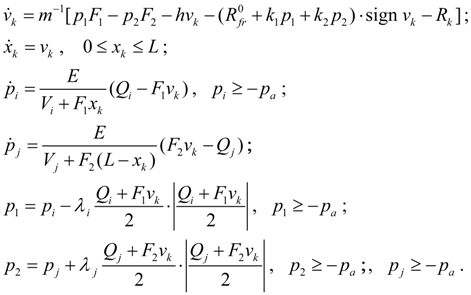
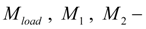 loading moments reduced to shafts of hydraulic motors in view of efficiency of mechanisms
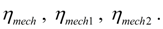
Hydraulic cylinder.
Dynamics of hydraulic cylinder with attached pressure head and drain pipelines (the simplified circuit – on Fig. 6) in view of the accepted assumptions can be described by the following system of equations:
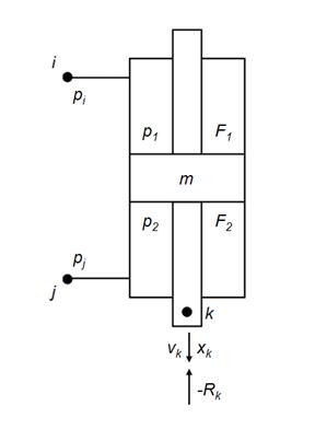
Fig. 6. Simplified circuit of hydraulic cylinder.
 (6)
(6)
Two in parallel connected hydraulic cylinders.
The mathematical model of two in parallel connected hydraulic cylinders (the simplified circuit is presented on Fig. 7) in view of the accepted assumptions looks like:
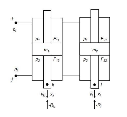
Fig. 7. Simplified circuit of two in parallel connected hydraulic cylinders.
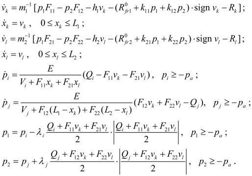 (7)
(7)
In the equations (6) – (7) the following designations are accepted:
 masses of mobile parts reduced to rods;
 pressures in cavities of hydraulic cylinders adjoining nodes
i
and
j
;
pressures in cavities of hydraulic cylinders adjoining nodes
i
and
j
;
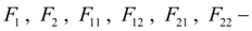 working areas of pistons in cavities of hydraulic cylinders;
 coefficients of viscous friction;
 speeds and movements of rods of hydraulic cylinders (nodes
k
and
l
);
speeds and movements of rods of hydraulic cylinders (nodes
k
and
l
);
 coefficients of proportionality between pressure in cavities of hydraulic cylinders and forces of friction in seals;
 values of friction forces in seals at absence of pressure;
 external forces to rods of hydraulic cylinders (nodes
k
and
l
);
external forces to rods of hydraulic cylinders (nodes
k
and
l
);
 values of maximal movement (stroke) of pistons;
 pressures in nodes
i
and
j
of pipelines adjoining cavities of hydraulic cylinders;
Е
– reduced module of elasticity of cavities with a working liquid;
pressures in nodes
i
and
j
of pipelines adjoining cavities of hydraulic cylinders;
Е
– reduced module of elasticity of cavities with a working liquid;
 minimal volumes of cavities and pipelines adjoining nodes
i
and
j
;
minimal volumes of cavities and pipelines adjoining nodes
i
and
j
;
 flows in nodes
i
and
j
;
flows in nodes
i
and
j
;
 reduced coefficients of losses of pressure on length in view of hydraulic resistance and geometry of pipelines.
Elastic-inertial loading.
Fig. 8. Simplified diagram of elastic-inertial loading at progressive motion.
At progressive motion
(Fig. 8) elastic-inertial loading is described by the equations:
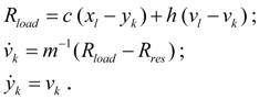 (8)
(8)
Fig. 9. Simplified diagram of elastic-inertial loading at rotating motion.
At rotating motion
(Fig. 9) elastic-inertial loading is described by the equations:
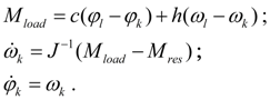 (9)
(9)
In the equations (8) and (9) the designations are accepted:
 accordingly force and moment of loading;
c
,
h
– rigidity and coefficient of viscous friction;
accordingly force and moment of loading;
c
,
h
– rigidity and coefficient of viscous friction;
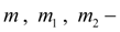
 accordingly force and moment of resistance;
m
,
J
– mass and moment of inertia of loading;
accordingly force and moment of resistance;
m
,
J
– mass and moment of inertia of loading;
 movement and speed of hydraulic cylinder rod (node
l
);
movement and speed of hydraulic cylinder rod (node
l
);
 movement and speed of mass (node
k
);
movement and speed of mass (node
k
);
 turn angle and angular speed of the hydraulic motor shaft (node
l
);
turn angle and angular speed of the hydraulic motor shaft (node
l
);
 turn angle and angular speed of rotating mass (node
k
).
turn angle and angular speed of rotating mass (node
k
).
Wheel carrier (wheel).
This block is necessary at carrying out of tractive-dynamic calculations of hydraulic volumetric transmissions of self-propelled wheel machines. The considered here mathematical model of wheel carrier describes rigid communication of a wheel with the hydraulic motor (Fig. 10
а
), i.e. possible elastic deformations of a gear and a shaft between a hydraulic motor and a wheel are not considered.
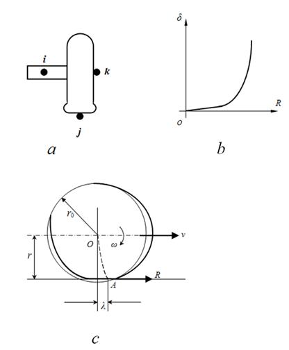
Fig. 10. Simplified scheme of dynamics of wheel.
а
– wheel,
b
– slipping curve,
c
– dynamic deformation of wheel
In view of accepted assumptions the mathematical model of dynamics of wheel (wheel carrier), looks like:
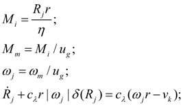 (10)
(10)
where
М
i
– a wheel moment in view of losses in a gear;
М
m
–moment on a shaft of hydraulic motor;
 – traction reaction (circular force) to a wheel;
r
– dynamic radius of a wheel;
– traction reaction (circular force) to a wheel;
r
– dynamic radius of a wheel;
 – efficiency and transfer number of a gear of a wheel;
 angular speeds of a shaft of hydraulic motor and a wheel;
 tangential rigidity of tire;
 function of slipping (Fig. 10
b
).
function of slipping (Fig. 10
b
).
Machine.
Dynamics of progressive motion of machine is described by system of the equations:
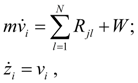 (11)
(11)
where
 mass, speed, movement and summer force of resistance to machine moving;
 traction reaction (circular force) on the
l
-th leading wheel in node
j
,
l
= 1, …,
N
;
N
– number of leading wheels (axes).
traction reaction (circular force) on the
l
-th leading wheel in node
j
,
l
= 1, …,
N
;
N
– number of leading wheels (axes).
|