|
Dynamics of braking processes in the main hydraulic drive of auto concrete pump SB-126А
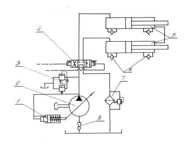
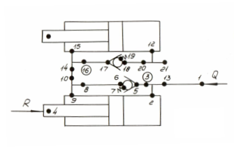
Fig. 1. At passage by the piston of the certain position in the end of a stroke cavities of the hydraulic cylinder incorporate, due to what there is an alignment of pressure and as a result – braking of the piston of the hydraulic cylinder. The return valve is necessary for division of cavities at dispersal of the piston.The important parameter providing the basic dynamic characteristics of braking process is a diameter of throttling apertures in the cylinder by means of which the cylinder chamber incorporates to the return valve. Objective of the given work was the background of a choice of certain diameter of throttling window providing braking of the piston of the hydraulic cylinder and its output to a stop at work both of piston, and of rod chamber [1, 5]. The existing design of the hydraulic cylinder has throttling apertures of various diameters: in a piston chamber – 2 mm, in a rod chamber – 3 mm. Expediently to have apertures of identical diameter at condition of provision of braking of pistons with its output to a stop at both possible diagrams of connection of the hydraulic cylinder to the pump installation: either a piston or a rod chamber.
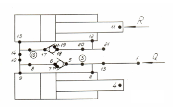
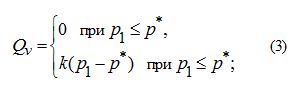
Fig. 2. Fig. 2 shows the rated diagram reflecting work of hydraulic cylinders of the main hydraulic drive during braking of pistons is resulted, that is at passage by the piston of position, at which both cavities of each hydraulic cylinder incorporate through the return valve. The case of connection of a rod chamber of the hydraulic cylinder with nodes 2–9–4 to the pump installation is considered. According to algorithm of the description of the hydraulic drive diagrams of any structure, accepted to the used program HYDRA of dynamic calculation of a hydraulic drive, the circuit diagram consists of 13 hydraulic elements connected in 21 nodes. The load from a column of a concrete mixture in a concrete pipeline R , operating directly to the second hydraulic cylinder rod (in node 11), is equal:
где
р
c
– a pressure of a concrete mixture in a concrete pipeline input;
F
c
– the area of the concrete
mixture cylinder piston.
where
р
* – an adjustment pressure of a pressure relief valve;
р
1
– a pressure in hydraulic system in node 1;
k
– a factor of a slope of the pressure relief valve static characteristic.
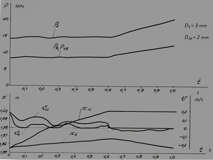
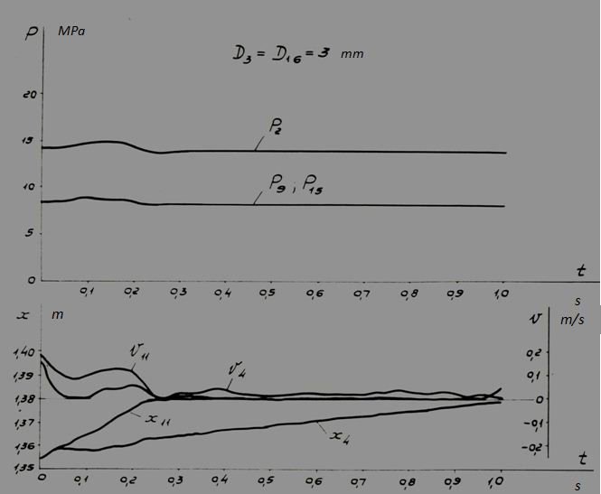
Fig. 3.
Fig. 4.
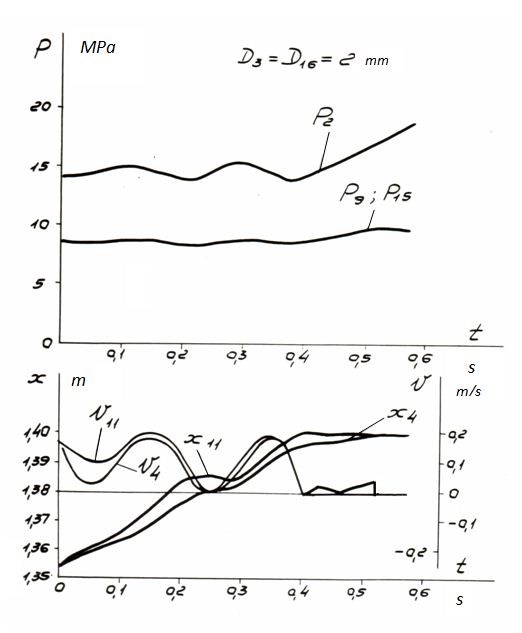
Fig. 5.
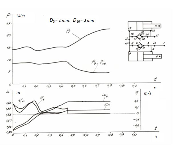
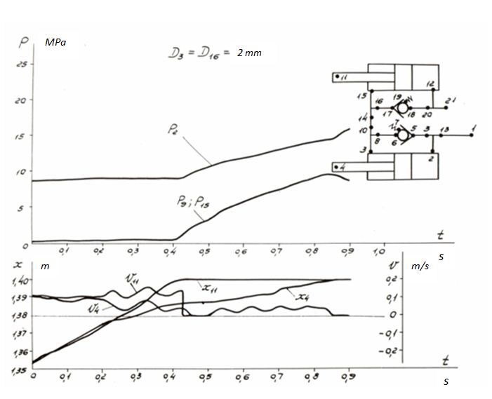
Fig. 6. Fig. 3 – 6 show results of dynamic calculation of process of braking of pistons of hydraulic cylinders at connection of pump installation to a rod chamber (see the diagram Fig. 2). Transients are presented in the form of graphs of variation of pressure in chambers of cylinders, speeds and movements to functions of time. The following designations are accepted: р 2, р 9, р 15 – pressures accordingly in nodes 2 (a rod chamber), 9 and 15 (piston chambers); х 4 , v 4 – accordingly movement and speed of a rod of the first hydraulic cylinder (node 4); х 11 , v 11 – similarly movement and speed of a rod of the second hydraulic cylinder (node 11); t – time.The calculation versions are received at the assignment of various diameters D 3 and D 16 of throttling apertures of hydraulic dampers (we’ll remind, that in the rated circuit diagram these parameters are adhered to nodes 3 and 16), specified on Fig. 3 – 6. Besides the specified basic rated versions one more version appropriating connection to the pump of a piston chamber of the first hydraulic cylinder has been considered in addition, its rated diagram is presented on Fig. 7.
Fig. 7. Difference of this diagram from previous consists also that load R from tractive resistance and the reduced mass of a concrete mixture column are enclosed here to a rod of the first hydraulic cylinder (node 4).As seen from the received results of calculation, the best version from the point of view of maintenance of braking of the piston at condition of movement up to the stop is the version at which both of diameter throttling apertures are equal 2 mm (Fig. 6). Both of the pistons reach up to the stop, process of braking lasts nearby 0.5 s, the maximal piston speed in a time of achievement of the end of the stroke does not exceed 0.05 m/s, dynamics of pressure is insignificant. In other versions either it is not provided movement of one of pistons up to the stop (Fig. 3, 4), thus is observed greater dynamics of pressure, or process of braking is too stretched on time (see х 14 , Fig. 5). Before to make a final choice of diameters of throttling apertures, it was necessary to inspect the chosen values of diameters at other circuit diagram of connection of hydraulic cylinders (Fig. 7).
Fig. 8. Results of this testing calculation (Fig. 8) have shown, as for this circuit diagram at chosen diameters of throttling apertures of 2 mm braking of pistons is provided at movement up to the stop, and the following parameters of process are observed: time of braking ~0.85 s, the maximal speed of the piston in a time of achievement of the end of the stroke is ~0.05 m/s, the peak pressure do not exceed 15.7 MPa.The carried out researches have allowed making the following conclusions. 1. The considered hydraulic system is very sensitive to variation of diameters of throttling apertures of existing damping devices of hydraulic cylinders, therefore a choice of these diameters at a design stage of the machine it should be made on the basis of the detailed dynamic analysis of braking processes, and it is desirable with optimization of parameters. 2. From the considered versions the best from the point of view of maintenance of braking at movement of pistons up to the stop and minimal dynamics of hydraulic system is the version at which both diameters of throttling apertures are equal 2 mm. 3. Alignment of pressures in cavities of hydraulic cylinders at connection of cavities by means of the return valve do not occur because of significant hydraulic resistance of the bypass channel, therefore effective braking with significant clearing speed of the piston on a short interval of time in one of the considered versions was not observed. At the small speeds of movement of the order of 0.2 m/s which are taken place in the considered rated versions, it is not so essential, however at greater speeds, the order 0.8 – 1 m/s, this circumstance should be considered. Therefore the choice of parameters of damping devices should be spent proceeding from the results received over a wide range of speeds and loads. |
Contents
>> Analysis and Design
>> Systems of Hydraulic Drives
>> Hydraulic Drives of Auto Concrete Pumps
>> Dynamics of breaking processes in the main hydraulic drive of the auto concrete pump SB-126A