|
Example
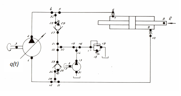
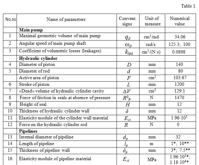
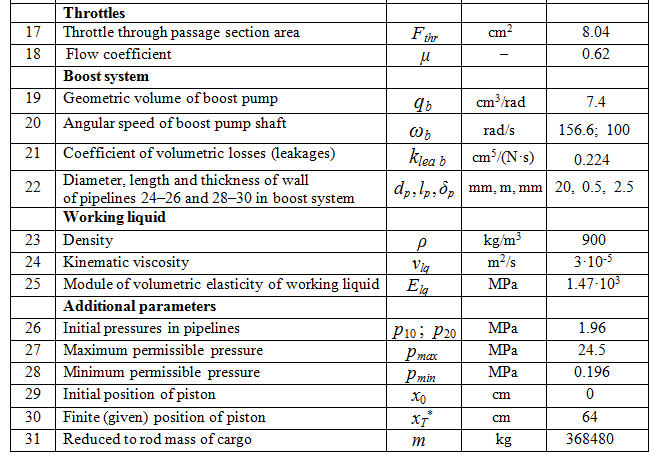
Fig. 5. As all necessary parameters of control ( Т I , Т II , Т III , q p , ... ) are calculated in advance and involved in the program of formation of external indignations PERTR, check of offered algorithm of control by numerical experiment (which objective to establish a degree of adequacy of the accepted key points) as in system HYDRA varied nonlinear communications of elements and parameters of a hydraulic drive are considered in most general view, such as is in essence realized: variable elasticity of cavities of the hydraulic cylinder, loss of pressure on length of pipelines and in local resistances, outflow of a working liquid from cavities of the pump, work of system of additional charging on dynamics of return valves, etc.Before to estimate a degree of influence of this or that factor on parameters of control (mainly, on the lowest natural frequency of hydraulic system), we'll consider main parameters of hydraulic system presented in tab. 1.
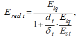
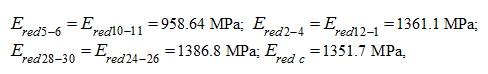
The reduced modules of elasticity of pipelines 5 – 6, 10 – 11, 2 – 4, 12 – 1, 28 – 30, 24 – 26 and cavities of the hydraulic cylinder (all – with a working liquid) are defined according to the formula (7) previous sections "Algorithm"
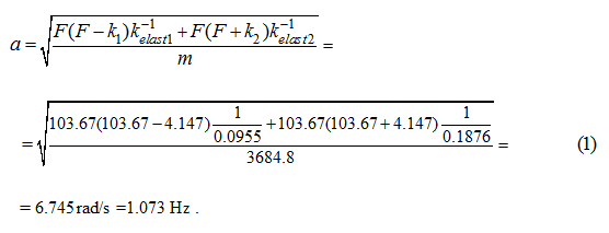
As the considered hydraulic system (Fig. 5) is symmetric, we'll accept Т III = Т I = 1.05 s, then according to expression (49) previous sections "Algorithm" :
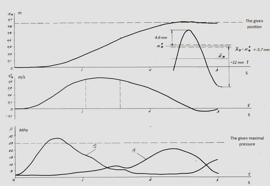
On Fig. 6 results of numerical experiment – modeling of transients in considered hydraulic system by means of the program HYDRA in using control with the parameters found above are resulted.
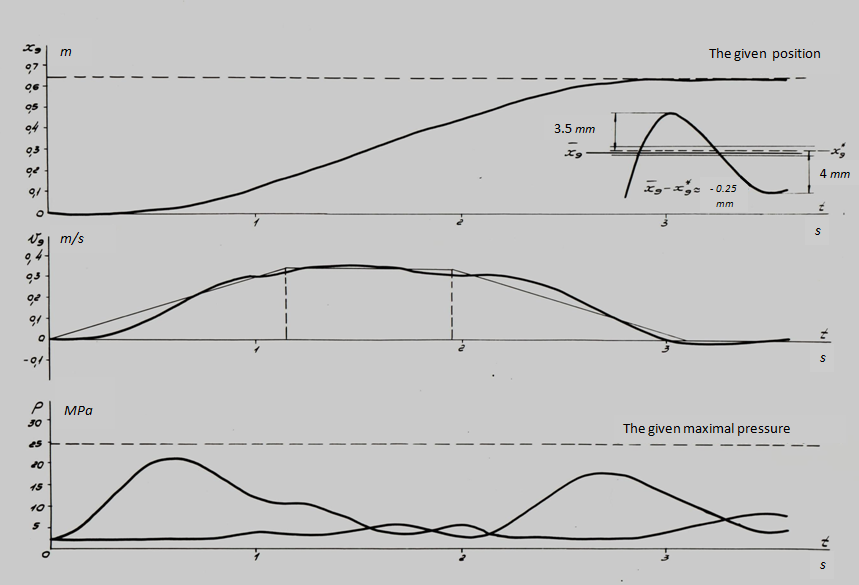
Fig. 6. Here diagrams of variation in time of movement х 9 and speed v 9 of the hydraulic cylinder piston (node 9 on Fig. 6), pressure р 1 and р 2 (accordingly in nodes 1 and 2), as well as set trapezoidal dependence q (t), reduced to type:
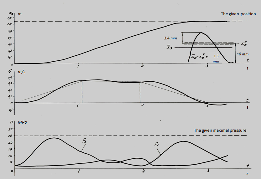
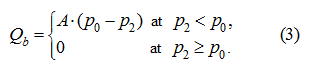
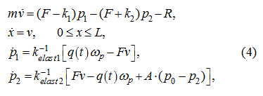
Fig. 7. Here, as well as earlier, v 9 , х 9 – speed and movement of the hydraulic cylinder piston (node 9), р 1 , р 2 – pressure in input and output of the basic pump (nodes 1 and 2). In comparison with the 1-st rated case the significantly better agreement of the given and actual parameters of control process is observed. So, over-pressure р 2 in the given rated case was equal to ~ 23 MPa, error of positioning is less about three (a deviation of the established position of the piston from the given one х 9 * = 64 cm have made ~ 1.3 mm), an oscillation property of transients has decreased. Improvement of parameters of control process is reached due to an insignificant increase of time Т II and general time of regulation Т (in this case Т = 3 s in comparison with 2.605 s in the previous example). However here again natural fluctuations are traced neatly, to extinguish which completely it is not possible. Last circumstance as already it was marked above, is connected with availability nonlinearities in considered hydraulic system (variable rigidity, oscillation property of boost system, etc.), not considered at synthesis of parameters of the control, lead on linear model. Nevertheless "hit" in a vicinity of a target point of positioning х 9 * with a margin error ε ≈ 1.3 mm for the given type of control (without introduction of correcting links with feedback by position, speed, etc.) can be considered as comprehensible. Increase of accuracy of positioning, including improvement damping properties of hydraulic system can be achieved really due to introduction of "precise" control by means of in appropriate way chosen correcting links.As already it was marked above, in the Appendix it is shown, that the account of variable factors of elasticity, losses of pressure on length of pipelines and in local resistances, leakages of working liquid almost does not influence on values of natural frequencies, however existing differences in character and numerical values of parameters of considered transients (planned values at synthesis of control and "actual" values at numerical experiment) testify to an indispensability of the account of boost system at construction of algorithm of control, at least a level of the task of the static characteristic of boost return valves. Therefore let's consider one more rated case, and natural frequency of hydraulic system we'll define in view of the static characteristic of the return valve in boost system. For this purpose the equation of flows [see the system of equations (5) in the previous section "Algorithm" ] in a drain pipeline of the hydraulic system we'll write in the form of:
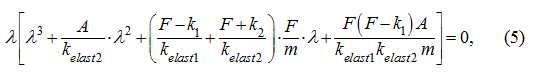
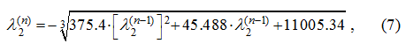
It is known, that among roots of the cubic equation, at least, one – real. We'll find it by iterative method :
With accuracy ε = 0.001 required root is equal λ 2 = – 375.357 and conforms a rapidly damped component of proper decision of the equations (4) (time constant ~ 0.003). Eigenvalues defining oscillation property of system, are found from the quadratic equation received by division of the polynomial (6) on the binomial λ ( λ + 375.357 ) : λ 2 + 0.043 λ + 29.348 = 0, (8) λ 3,4 ≈ – 0.0215 ± 5.42 i , (9) whence a natural frequency of the hydraulic system is equal а = 5.42 rad/s = 0.862 Hz. The found value practically coincides with the least observed one (5.46 rad/s) as a result of modeling dynamics of the hydraulic system by the program HYDRA. The factor of damping ν = 0.0215 testifies underdamping of natural fluctuations (logarithmic decrement in this case makes
Results of modeling of the last rated version are resulted on Fig. 8.
Fig. 8. Here required accuracy of positioning of 0.5 mm is received(a deviation of an equilibrium position of the hydraulic cylinder pistonThe considered examples show, that at a stage of "rough" control realization of the offered algorithm of multiple periods of natural fluctuations, is possible in the main, however an availability of some essentially nonlinear effects does not allow determining a natural frequency of hydraulic system enough precisely. So, changeability of elastic properties of drive in process of movement of the hydraulic cylinder piston leads to variation of frequency of natural fluctuations, and means, that the actual system is not completely adequate to linear model with constant factors. Besides a hydraulic system with volumetric regulation is slightly damped. Therefore for achievement of high accuracy of positioning it is necessary: 1) to increase a damping degree of a hydraulic drive; 2) to enter correcting links at a stage of "precise" control with feedback by position and speeds of the piston, and it may be - on acceleration (pressures in the hydraulic cylinder cavities). It is not excluded, that the decision of both problems can be reached by introduction of appropriating feedback. |
Contents
>> Engineering Mathematics
>> Control Systems
>> Dynamic Synthesis of Control System of Hydraulic Drive
>> Synthesis of control by a power hydraulic drive of volumetric regulation
>> Method of multiple periods of natural vibrations
>> Example