|
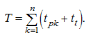
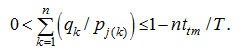
Control of the flow-transport system Let's consider a problem of calculation of processes of supply of aggrigates of concrete to account bunkers of concrete plants. We'll assume, that process of dozing of aggrigates at concrete mixing plants has a stable character. Therefore as the model describing the basic strategy of control by concrete mixing plants facilities, we accept a periodic model with a constant updating, applied usually in conditions of stable demand [1]. Possible random deviations in the system which dispersion is insignificant, should be compensated in special control mode – a correction mode .Problem of control is maintenance of uninterrupted consumption of concrete aggrigates from account bunkers of concrete mixing plants. Therefore the condition of maintenance of a material stock in account bunkers in the given limits is entered. Duly loading of bunkers and inclusion of necessary mechanisms of the system (feeders in storehouses of aggrigates, the mobile reversive conveyors, dumping carriages, switching centres, etc.) should exclude impact of various flows of aggrigates on conveyor lines. Input data are: the rated expenses of feeders and dozing devices, transport delay for each device of the system (time of moving of a material from a storehouse up to an appropriating arrangement), the top and bottom levels of a material stock in bunkers, initial material stocks in bunkers, structure of the conveyor transport scheme. Control variables are instants and duration of inclusion of feeders in storehouse of aggrigates. At control of the bunkers loading system one of the following modes is realized: – the stationary (periodic) mode of loading appropriating a stable demand for aggrigates; – a transitive (starting) mode of loading; – the correction mode necessary for the compensation of mistakes cumulative in system, leading to a deviation of actual materials stocks in bunkers from the rated ones. Let's consider consistently each of these modes. Let's enter following designations: k – a number of bunker ; j ( k ) – a number of storehouse, from which an aggrigate moves into the k -th bunker; p j(k) – an expense of feeders of the j ( k ) -th storehouse, t/min ; q k – an expense of dozing device of the k -th bunker, t/min ; V sk and V mk – accordingly the top and bottom limits of a material stock in the k -th bunker, t ; τ k – transport delay for the k -th bunker, min ; σ ij – transport delay between the i -th and the j -th storehouses, min ; t pk – duration of loading of the k -th bunker in a stationary mode, min ; t t – technological interval on the conveyor tape between adjacent portions of materials, min ; T – the cycle time, min ; V 0k – an initial material stock in the k -th bunker, t ; t k (m) – an instant of the m -th inclusion of feeder at supply of aggrigate into the k -th bunker, min ; V hc – useful volume of the heating-cooling bunker, t ; s pk – duration of loading of the k -th bunker in a transitive (starting) mode, min ; V k ( t ) – a current value of a material stock in the k -th bunker, t ; Δp rk – an error in expense of a feeder of the k -th bunker during the r -th cycle, t/min ; Δq rk – an error in expense of a dozing device of the k -th bunker during the r -th cycle, t/min ; Δt pk – an error in duration of feeding of the k -th bunker, мин ; θ k – an increment of duration of feeding of the k -th bunker in a correction mode, min . The stationary (periodic) mode Construction of algorithm of control is based on a structure of the scheme of conveyor lines [2]. Each technologically independent site of the scheme represents either a junction when flows of materials from storehouses pass all through one main conveyor, or a network , when flows of materials are distributed by the branched system of conveyor lines.For junction with n account bunkers at stationary process of unloading the cycle time is
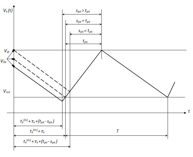
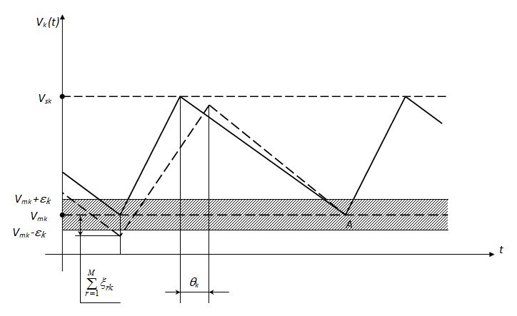
Fig.5. Variation of material stock in a bunker in the transitive
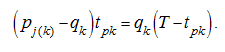
On Fig.5 the graph of stationary process of variation in time of a material stock in a bunker V k ( t ) is resulted. It is accepted, that taking of material away from a bunker goes on uninterruptedly. From the mode stationarity follows, that an increase of a material stock in a bunker during its loading is equal to the stock reduction during unloading:
Let's define now instants of inclusion and shutdown of feeders in a stationary (periodic) mode.
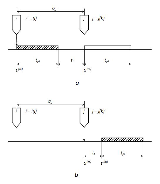
Fig.6. To the conclusion of the equation of the graph of inclusions of feeders:
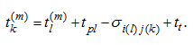
Let the k -th bunker is loaded from the j -th storehouse, and the l -st bunker – from the i -th storehouse. If the fraction of aggrigate, acting from the i -th storehouse, on a tape of the conveyor follows fraction of a aggrigate from the j -th storehouse (Fig.6, а ), then feeders of the i -th storehouse should be included so that in an instant of shutdown of feeders of the j -th storehouse between portions of fillers on the conveyor tape the interval t t has been provided. As the distance between the i -th and j -th storehouses (or difference of their distances up to a central point in which flows of materials are united) may be expressed by transport delay σ ij , then instants of inclusion of feeders are connected by dependence:
An instant t 1 ( m ) of the m -th inclusion of feeders of the 1-st bunker is determined by the condition of implementation of the ( m –1)-th cycle, and an instant t 1 (1) of the 1-st inclusion depends on the initial state of the system. After calculation of duration of loading of the k -th bunker it is necessary to specify the lower limit of the material stock:
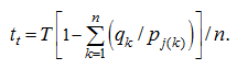
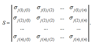
Let's consider now the scheme site, being a network. We'll notice, that a network can be considered as set of junctions technologically connected among themselves. Calculation of a site of such structure is carried out basically on the same dependences, but requires some additions. First of them consists that for definition Т the expression in square brackets in the formula (1) is minimized on all bunkers entering into a network. Then all junctions making the given network and technologically connected among themselves, will work in a general periodic mode. Other addition to calculation consists in coordination of technological intervals calculated for various junctions, entering in a network. It is necessary for the coordination of instants of supply of aggregates with objective of exception of a possibility of impact of various fractions in reloading points of a network (that is there where there is an association of various flows). For this purpose it is possible, for example, having calculated t t for each junction under the formula (6) and having defined a minimum, to accept it as a technological interval on all junctions of a network. If in system it is stipulated warming (cooling) of materials then the material portion volume which is given out from a storehouse, should not surpass useful volume V hc of the heating-cooling bunker:
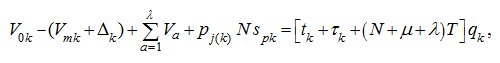
The transitive (starting) mode Let the system initial state is characterized by a stock of material V 0k in the k -th bunker (Fig.5). Then duration of loading s pk of the k -th bunker in a transitive mode is defined from the equation:
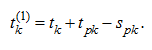
Instants t k (1) of inclusion of feeders in the transitive mode are defined by recalculation t k :
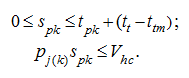
The transitive (starting) mode with duration of loading s pk is considered realizable if the following conditions are satisfied:
Besides it is necessary, that the material stock in the bunker in an instant of beginning of its loading was not below a critical level, that is, otherwise, would not be the bunker emptying. Default of any of these restrictions entails an indispensability either increasing N , or preliminary loading of the bunker at the termination of batching of fillers at concrete plants. The correction mode During transportation of materials from storehouses in bunkers there will be deviations from rated parameters in the system, that finally will lead to a deviation of actual stocks of materials in bunkers from the rated ones. These errors result from a lot of the reasons:– non-uniformity of supply of materials by feeders; – elimination of a part of materials as a result of sorting in department of control screening; – possible losses of a material on the way; – non-uniformity of expense of dozing devices; – mistakes in duration of inclusion of feeders, etc. As a result mistakes in the system will be accumulated and at achievement maximum permissible deviations it is necessary to compensate them in a so-called correction. This mode represents the "deformed" stationary mode in which duration of supply of a material in the bunker is a little bit changed, but within the limits of performance of conditions (16). Thus, variation of duration of bunkers feeding at correction is carried out either due to reduction of a technological interval up to minimally admissible, or due to reduction of feeding duration. Clearly, that in a similar way it is possible to carry out the compensation of only insignificant deviations in the system.
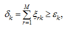
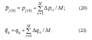
Fig.7. Variation of material stock in a bunker in the correction mode. Let to instant of beginning of loading of the k -th bunker in the correction mode (Fig.7) a total error for the past М cycles of the stationary mode has made
Thus
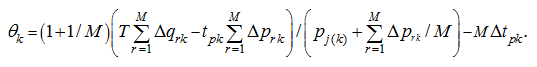
The basic equation of the correction mode can be received proceeding from the condition, that after carrying out of correction the beginning of next loading (in a stationary mode) corresponds to the bottom level of material stock in a bunker (a point А on Fig.7). Then
Thus, the developed method of preparation of algorithm for calculation of complex flow-transport system of loading bunkers allows to design in some optimum way the scheme of conveyor transport and to choose its parameters. Executed on an example of the actual scheme of concrete mixing plants facilities calculations have allowed to estimate possibilities of control of the transportation system on various modes. |
Contents
>> Engineering Mathematics
>> Control Systems
>> Control of Flow-Transport System of Concrete Mixing Plants
>> Control of the flow-transport system
 (3)
(3)
 (5)
(5)
 (6)
(6)
 (8)
(8)
 (9
а
)
(9
а
)
 (11)
(11)
 (14)
(14)
 (15)
(15)
 (16)
(16)
 (17)
(17)
 (22)
(22)