Contents >> Engineering Mathematics >> Control Systems >> Control of Flow-Transport System of Concrete Mixing Plants >> Structural analysis of the transport scheme

Engineering Mathematics - Control Systems - Control of Flow-Transport System of Concrete Mixing Plants - Structural Analysis

Structural analysis of the transport scheme

The concrete mixing plants facilities on construction of large industrial objects represents the complex technological system consisting of a network of conveyor lines, storehouses concrete aggregates, departments of control screening, heating-cooling, dehydration, account bunkers.
Two versions of technological schemes of supply of materials by conveyor transport from storehouses to account bunkers of concrete plants are possible (Fig.1).


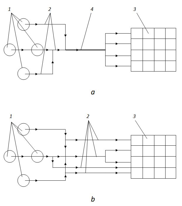
Fig.1. Basic schemes of conveyor transport.
1 – storehouses; 2 – a conveyor; 3 – bunkers; 4 – the main conveyor.

In the first case (Fig.1, a ) the materials coming from a storehouse or from group of storehouses, move to account bunkers by system of tape conveyors, and for this scheme availability of the main conveyor uniting all flows of materials is characteristic. In the second case (Fig.1, b ) the materials coming from storehouses, are not united in one flow, that is the main conveyor is absent.


Fig.2. Possible versions of transport routes.
m 1 – m 7 – routes; 1 – 35 – conveyors.

Route – the sequence of conveyors (Fig.2), transporting materials from same storehouse (for example, m 1 = { 1, 2, 3, 4, 5, 6, 7 }; m 2 ={ 8, 3, 9, 10 }).
Intersection of routes – the conveyor or group of conveyors entering in some routes (for example, 3, 6, 23 ).
Union of routes – the set of all routes having the given intersection (for example, m 1 U m 2 ; m 1 U m 3 ; m 5 U m 6 U m 7 ).
Connection – the route entering at the same time in some unions (for example, m 1 ; m 3 ).
Network – the set of unions of routes, constructed thus that for any union at least, one union (distinct from the given), having with it connection, will be (Fig.2, а ).
Junction – the union of routes which is not having connections with other unions (Fig.2, б ).
The general scheme of conveyor transport may be divided into subschemes which structure conforms either to unit (Fig.1, а ), or to network (Fig.1, б ).
The accepted definitions we'll use at the structurel analysis of the actual scheme of conveyor transport (Fig.3).


Fig.3. The actual scheme of conveyor lines of concrete mixing plants facilities.

According this scheme aggregates of concrete (sand, gravel, road metal) various fractions move from storehouses C i by conveyor lines k l to concrete plants of cyclic ( I ) and continuous ( II ) action. In points A j and B j flowss of materials are accordingly divided or united. The initial information about structure of the considered transport scheme is shown in tab.1.


Two basic versions of the technological scheme are possible: the first – with supply on a plant of cyclic action only gravel; the second – with supply on this plant road metal, and gravel too.
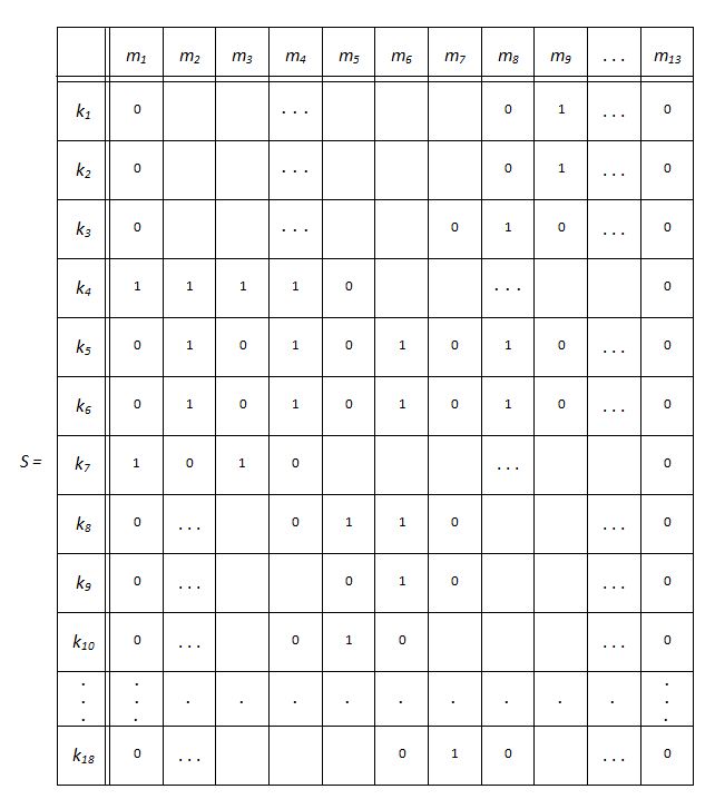
The scheme (Fig.3) and tab.1 provide a possibility of use of road metal at a plant of cyclic action as a aggregate for some marks of concrete. The structural analysis of the transport scheme we'll execute for its first version.
To establish interconnection between separate routes, we'll draw up on the basis of tab.1 the following matrix S :


The matrix is constructed as follows. If on intersection of the l -th line and the j -th column of the matrix 1 is it means, that the l -th conveyor line enters into the j -th route, otherwise the lj -th element of the matrix S is equal to 0.
Let's consider the matrix S structure in greater detail. The conveyor k 1 enters only into the route m 9 , therefore the ninth element of the first line is equal 1, and other elements – zeros. On the other hand, the route m 2 consists of conveyor lines k 4 , k 5 , k 6 . In the matrix S it is shown that the fourth, fifth and sixth elements of the second column are equal to 1.
Using the matrix S , we define intersections, unions of routes and connections. If in the l -th line of the matrix S , appropriating to the conveyor line k l , two or more unit elements are available the given conveyor line is intersection of those routes which columns are conformed with these elements. For example, the conveyor line k 4 is an intersection of the routes m 1 , m 2 , m 3 , m 4 , and the conveyor line k 6 is an intersection of the routes m 2 , m 4 , m 6 , m 8 . Conveyors k l and k 2 also can be considered as an intersection, as enter into the isolated route m 9 .
The set of the routes u 2 = m 1 U m 2 U m 3 U m 4 is a union of routes on the intersection k 4 , the set of the routes u 3 = m 2 U m 4 U m 6 U m 8 – a union of routes on the intersection k 6 , etc.
For the union u 3 all its four consisting routes – connections: m 2 and m 4 enter into the unions u 2 and u 3 ; m 6 - into u 3 and u 5 ; m 8 – into u 3 and u 9 (tab.2).


Analyzing connections m k , we come to conclusion, that all routes of the transport scheme are divided on three sets not connected among themselves: 1 – unit (route m 9 ); 2 – network (routes m 1 , m 2 , ..., m 8 ); 3 – a network (routes m 10 , m 11 , m 12 , m 13 ).


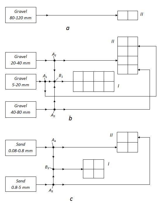
Fig.4. Technologically independent sites of the transport scheme.

In the actual transport scheme it conforms to breakdown of the scheme on technologically independent three sites (Fig.4): transportation of gravel of fraction 80 - 120 mm - unit (Fig.4, a ); transportation of gravel of fractions 5 - 10, 10 - 20, 20 - 40 and 40 - 80 mm - network (Fig.4, b ); transportation of sand - network (Fig.4, c ).

The control by transport flows of aggregate to account bunkers on three received sites can be carried out independently.


< Previous Contents Next >