|
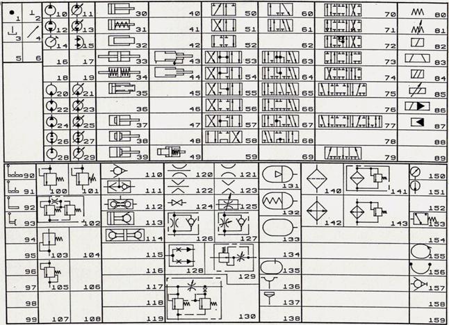
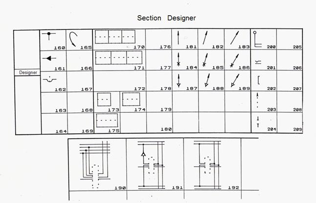
Library of standard graphic symbols of elements of hydraulic circuits Analysis of big number of hydraulic circuits, corresponding standards and engineering specifications of factories and firms-manufacturers allows to allocate limited number of graphic symbols (fragments of hydraulic circuits), more often meeting in circuits of hydraulic drive. On a basis of it the special library of standard graphic symbols of hydraulic elements which application enables has been created to make circuit, not spending time for portrayal of these elements. Such technology under condition of permanent job with the automated system allows to facilitate work of designer, having released him from significant part of routine work to raise his productivity and, the main thing to enable him to concentrate on a creative direction during designing. For convenience of work of user images of all symbols of libraries it is expedient to place on pages of the special MENU-HELP (Fig. 1).
Fig. 1. Library of graphic symbols of elements of hydraulic circuits
Into the section «Basic symbols» standard graphic representations of basic functional elements of hydraulic circuits enter. These symbols are applied at synthesis of hydraulic circuits more often and consequently are located on the first page of the MENU-HELP. Division of symbols of the given section into groups to a functional attribute and original through numbering of symbols help fast storing of numbers of symbols and convenience of work with library. The following groups of hydraulic elements are included in this section: «Pumps and hydraulic motors» , «Hydraulic cylinders» , «Directional control valves» , «Valves» , «Throttles» , «Other elements» . Into group «Pumps and hydraulic motors» (Fig. 2) pumps (numbers of symbols 10 to 13); manual pump 14; rotary hydraulic activator 15; hydraulic motors 20 … 23; pump-motors 24 … 29 enter. For all symbols, except for 14 and 15, the following rule is observed: numbers of not regulated hydraulic devices – even; similar adjustable – on unit it is more. Places where it is possible to represent a shaft or a control symbol (Fig. 2) on the circuit are shown by template lines.
Fig. 2. Group «Pumps and hydraulic motors»
Into group «Hydraulic cylinders» (Fig. 3) cylinders with unilateral rod (numbers of symbols 30, 31); plunger hydraulic cylinder 32; cylinders with bilateral rod 33, 34; cylinder with a supply of liquid through a rod 35; cylinders with damping devices 37 … 39; telescopic hydraulic cylinders 43, 44; power regulator 49 enter. Unlike pumps and hydraulic motors sites of pipelines are not included in symbols of hydraulic cylinders. Places where it is desirable to bring pipelines are allocated on the screen by white points that leads to the best appearance of principal hydraulic circuits.
Fig . 3. Group « Hydraulic cylinders »
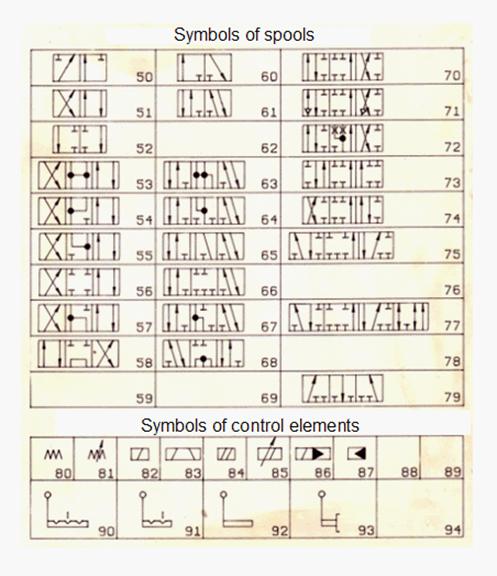
In group «Directional control valves» (Fig. 4-5) symbols of spools (numbers 50 to 79, Fig. 4); symbols of control elements (numbers 80 to 92, Fig. 4). To add in the circuit directional control valve, it is necessary to add all over again a symbol of a spool, and then – symbols of control elements. Examples of construction of directional control valves are resulted on Fig. 5.
Fig . 4. Group «Directional control valves» (symbols of spools and control elements)
Fig. 5. Examples of construction of directional control valves Into group «Valves» (Fig. 6) pressure relief valves (numbers of symbols 100 to 102); reducing valve 103; differential valve 105; check valve 110; valve of type «OR» 111; valve of type «AND» 112; pilot operated check valves 113, 114 enter. As well as in hydraulic cylinders, places in which it is desirable to bring pipelines are allocated on the screen by white points. Valve devices which are carrying out functions of regulators of flow do not enter into group «Valves» .
Fig. 6. Group «Valves»
Into group «Throttles» (Fig. 7) not adjustable throttles (numbers of symbols 120 to 123); valve 124; adjustable throttle 125; flow divider 128; flow regulators 129, 130 enter. Symbols 121, 123 are convenient to use, if it is necessary "to insert" a throttle into already drawn fragment of the circuit.
Fig. 7. Group «Throttles»
Into group «Other elements» (Fig. 8) hydraulic accumulators (numbers of symbols 131 to 133); tanks and their elements (numbers of symbols 135 to 137); filters 140, 141; heat exchangers 142, 143; manometer 150; thermometer 151; relay of pressure 153; rotary connection of pipelines 155; high pressure sleeve 156; quick disconnect hydraulic connection 157.
Fig. 8. Group «Other elements»
Most often meeting auxiliary graphic symbols of circuits and basic elements enter into section «Designer» . With their help it is possible to build distributing of pipelines, to create new symbols or typical fragments of hydraulic circuits. There is a need of creation of new directional control valves more often. It is oriented on it the most part of symbols of the given section. If necessary new symbols of directional control valves is possible to bring in so-called library of additional symbols. Symbols of the section «Designer» are located on the first and second pages of MENU-HELP (Fig. 1). In the section there are the following groups of symbols: «Symbols of the first necessity» , «Symbols of distributing of pipelines» , «Symbols for directional control valves and valves» .
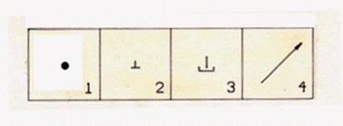
Symbols of «the first necessity» (Fig. 9) more often meet in hydraulic circuits, therefore they are born on the first leaf of the MENU-HELP (Fig. 1): 1 – a point in a place of crossing of pipelines; 2 – « deadlock » or cap on the pipeline end (this symbol more often meets in directional control valves); 3 – a tank (this symbol usually specifies plum into hydraulic tank); 4 – an arrow (this symbol is required, if, for example, it is necessary "to transform" the no controllable pump in adjustable).
Fig. 9. Group of symbols of «first necessity»
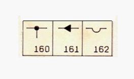
Symbols of distributing of pipelines are applied rather seldom, they are located on the second page of MENU-HELP and have numbers with 160 on 164 (Fig. 10).
Fig. 10. Symbols of distributing of pipelines
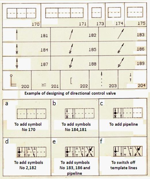
Symbols for directional control valves and valves. Group «Directional control valves» has undressed «Basic symbols» covers a significant part of designs of serially released out spools, however, there are also directional control valves other, more complex designs of spools. Practically any non-standard directional control valve can be constructed by means of group of symbols for directional control valves and valves have undressed «Designer» (Fig. 11).
Fig . 11. Group of symbols for directional control valves and other valves
Symbol of spool on the circuit consists of framework (numbers 170 to 175) and elements of schematic image of channels of spool in each of its positions (numbers of symbols 181 to 189). Orienting on template line which is passing on the center, it is convenient to build the directional control valve image. The symbol with number 203 is applied, if it is required to add to line representing the channel of spool, an arrow showing direction of flow. Symbols with numbers 200...202 are applied to construction of elements of manual control by directional control valves. Symbol 204 is added to symbols of pilot operated check valves 113 and 114 if it is required to receive the image of pilot operated check valve with unloaded rod (Fig. 12).
Fig. 12. Types of pilot operated check valves
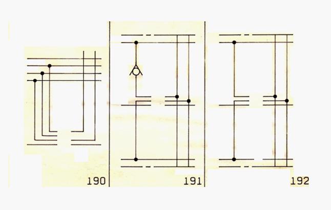
Symbols with numbers 190 to 199 (Fig. 13) form the group «Fragments of distributing of monoblock and section directional control valves» . Symbols of this group are born on the second leaf of the MENU-HELP (Fig. 1).
Fig. 13. Group «Fragments of distributing of monoblock and section directional control valves»
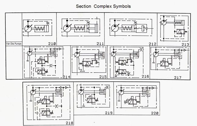
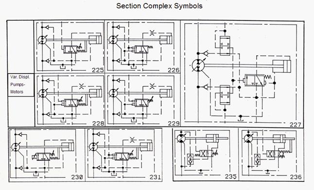
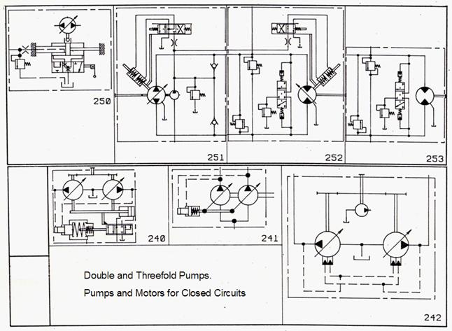
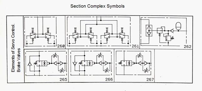
In section «Complex symbols» graphic representations of those elements of hydraulic circuits enter which consist of several more simple elements, but are structurally executed in the form of one unit. Symbols of this section are represented on Fig. 1. The section consists of the following groups: «Variable displacement pumps » (symbols with numbers 210 to 220); «Variable displacement pump-motors » (symbols with numbers 225 to 236); «Double, threefold pumps» (symbols with numbers 240 to 242); «Pumps and motors for closed circuits» (symbols with numbers 250 to 253); «Elements of servo control» (symbols with numbers 250 to 253); «Brake valves» (symbols with numbers 265 to 267). |
Contents
>> Engineering Mathematics
>> Hydraulic Systems
>> Synthesis of Hydraulic Circuits
>> Library of standard graphical symbols of hydraulic elements