|
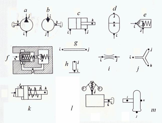
Structure description of arbitrary hydraulic circuits Analysis of various hydraulic systems applied in mobile machines (cars, road, building, digging-transport machines, tractors, etc.), shows, that there is finite set of base hydraulic elements by means of which it is possible to synthesize practically any circuit of hydraulic drive. These elements are: pump, hydraulic motor, hydraulic cylinder, valves of direct and indirect action, throttle (local resistance), pipeline (including, deadlock site of pipeline or cavity), tee (divider or adder of flows), power regulator, hydraulic accumulator, diesel engine with a centrifugal regulator, wheel carrier. Static calculation of any hydraulic circuit is reduced to definition unknown pressures, liquid flows (submissions), speeds and positions of mobile parts in points of connection of hydraulic elements – nodes of circuit. Thus of the same node can be simultaneously output of one element and input of another. Any hydraulic circuit can be considered as set of elements making it and nodes – points of connection of these elements. Each element of hydraulic circuit can be presented in form of a three-node element with nodes i (input), j (output) and k (control or transformation of energy), connecting it with other elements of the circuit. At stationary operating mode of hydraulic system spools of directional control valves borrow the fixed positions corresponding their certain working places, therefore directional control valve is considered as set of local resistances (throttles) according to position taken by it.
Fig. 1. Base elements and their nodes a – pump, b – hydraulic motor, c – hydraulic cylinder, d – hydraulic accumulator, e – valves of direct action, f – valves of indirect action, g – pipeline, h – deadlock site of pipeline (cavity), i – throttle (local resistance), j – tee , k – power regulator , l – diesel engine with a centrifugal regulator, m – wheel carrier. The input and output of element are defined by the accepted direction of working liquid flow. At change of direction of flow signs on corresponding parameters describing work of element (pressure difference, liquid flow, etc.) change. According to it the following classification of nodes of base hydraulic elements is accepted. Here a diesel engine as the most widespread type of drive engine in mobile machines is presented also. Table 1. Classification of base hydraulic elements nodes
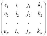
According to the classification each type of element has a special name – the identifier that allows at forming of the hydraulic system general model to select from library of mathematical models of hydraulic elements the request group of equations, namely: mathematical model of this type element. The selected basic identifiers of hydraulic elements: PUMP (pump), MOTOR (hydraulic motor), CYLINDER (hydraulic cylinder), PIPELINE (pipeline), VALVE (valve of direct action), etc. According to the entered identification each element e of hydraulic circuit concerns to the certain type with corresponding nodes i , j , k . Then structure of any hydraulic circuit after numbering all nodes is described by the following matrix S :
S
=
where e 1 , …. , e N – elements of hydraulic circuit, N – their quantity. The identifier e m defines mathematical model corresponding this element, and numbers of nodes i m , j m , k m serve for indexation of variables and as consequence – establishments of conditions of communication of elements with each other. For example, if output of element e m is at the same time input of element e n then it is obvious, that j m = i n and therefore, variables in output e m and in input e n coincide, i.e. the corresponding condition of communication takes place. As a result of such description of structure of circuit those equations by which elements entering into circuit are described, will be chosen from the general library of mathematical models of elements and indexation of variables entering into these equations (condition of communications), will be established on a basis of numbering nodes of elements specified in matrix S . The unique element which is dropping out of the general concept of a three-node element, is directional control valve as the number of nodes adjoining it can be more than three. Therefore within limits of static calculation we’ll consider directional spool valve as group of local resistances – possible connections of its nodes. Thus, description of structure (topology) of any arbitrary hydraulic circuit for carrying out of static calculations is formalized by: - drawings of nodes – points of connection of elements on simplified circuit, and numbering of nodes; - forming of structural matrix S on a basis of identification of base elements and numberings of their nodes in the circuit. |
Contents
>> Engineering Mathematics
>> Hydraulic Systems
>> Static Analysis
>> Structure description of hydraulic circuits