|
Example. Static calculation of hydraulic volumetric tranfer Let's consider widely widespread volumetric hydraulic transfer with closed circulation of flow which is usually applied in a drive of transmissions of mobile machines, and also for drive of various kinds of winches, turn mechanisms of cranes, excavators, etc.
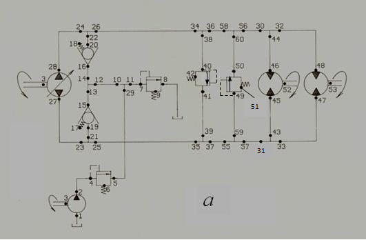
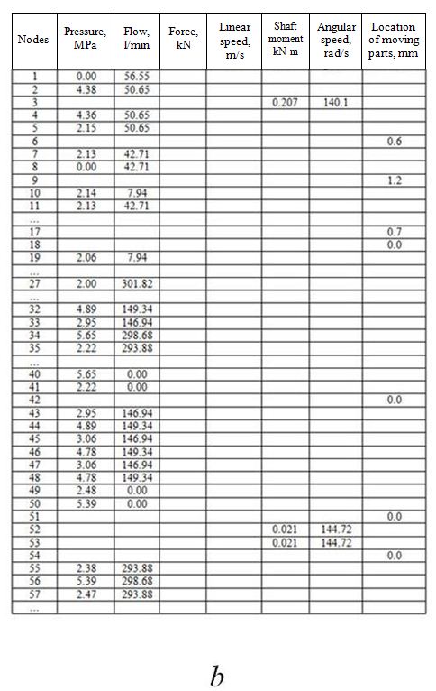
Fig.6. Simplified circuit of volumetric hydraulic transfer ( a ) and results of static calculation ( b ) On Fig. 6 а the simplified circuit of volumetric hydraulic transfer with closed circulation of flow, with one basic pump (27-28-3) and two hydraulic motors (46-45-52) and (48-47-53) is shown. For regulation of speed and change of hydraulic motor shaft rotation direction in a drive the variable displacement reversive pump is used. Hydraulic transfer is supplied by pressure relief valves and boost system including a constant displacement pump (1-2-3), and also check, overflow and pressure relief valves. For complex systems static calculation represents special interest. First, in some cases it is necessary for reception of mechanical characteristics, secondly, for diving of exact initial conditions at carrying out of next dynamic analysis, thirdly, for a choice of equipment at carrying out of experiments, and at last, for a choice of the certain standard sizes of hydraulic elements during design stage of hydraulic drive. Let's consider a problem of static calculation of hydraulic volumetric transfer of the mobile machine (Fig. 6 а ). The circuit contains 45 elements and 60 nodes. As a result of linearization of equations of hydraulic elements, structure analysis and minimization of number of variables the circuit is described by the 76-th order system of linear algebraic equations. Basic parameters of the hydraulic system: basic pump: 207.32 boost pump: gear pump with geometric volume 46 cm 3 hydraulic motors : 210.25 valves (valve box): 502.32 pipelines: high pressure sleeves: diameter 20 mm, lengths (28-24) and (23-27) – 1.2 m, (32-48), (44-46), (47-33) and (45-43) – 2.13 m; steel pipelines: diameter 18 mm, length (2-4) – 2 m, (5-29) – 1 m, rest – 0.2 m; tees: diameters in nodes of tees: (30-32-44), (43-33-34) – 20 mm, rest – 18 mm, coefficients of local resistance of branches of tees: (13-14-12), (29-10-11) – 1.0, 1.0, 1.0; (30-32-44), (43-33-34) – 10.0, 10.0, 10.0; rest – 0.6, 0.6, 0.6; working liquid: density – 900 kg/m³, kinematic viscosity – 3·10 -5 m²/s. As a result of linearization of the equations of hydraulic elements, the structural analysis and minimization of number of variables the diagram is described by system of the linear algebraic equations of 76-th order. Final results of static calculation (fig. 6б) have been received for 5 iterations (Fig. 6 b ). |