|
Typical structures of hydraulic circuits and their description The decision of the problem is based on representation of structure of the hydraulic circuit in the form of set of separate components – functional blocks of which practically any hydraulic circuit (Fig. 1) usually consists. There are: a diesel engine, pump station of open type (with an opened flow circulation), pump station of closed type (with a closed flow circulation), hydraulic actuators (hydraulic motor, two in parallel connected hydraulic motors, hydraulic cylinder, two in parallel connected hydraulic cylinders), various kinds of loading (elastic-inertial of forward or rotary action, wheel carrier), machine (block of simulation of progressive machine motion at tractive-dynamic calculations). Each of listed functional blocks is described by system of mixed differential and algebraic equations.
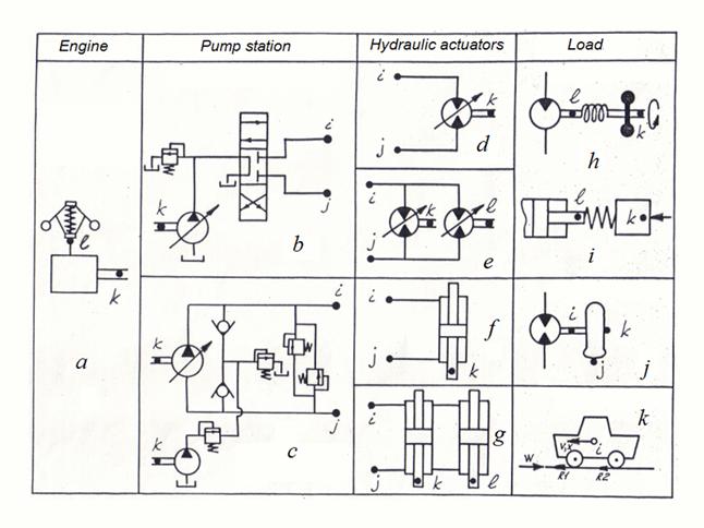
Fig.1. Functional blocks of hydraulic systems. a – diesel engine with centrifugal regulator; pump stations: b – with opened flow circulation, c – with closed flow circulation; hydraulic actuators: d – single hydraulic motor, e – two in parallel connected hydraulic motors, f – single hydraulic cylinder, g – two in parallel connected hydraulic cylinders; elastic-inertial loading: h – of forward action, i – of rotary action; j – wheel carrier, k – machine In a basis of the structural description of the hydraulic circuit an identification of functional blocks and representation lays, that each of them has no more than four nodes (points) in which it incorporates to other blocks of the circuit (Fig.1). The binding of nodes and identification of functional blocks are carried out as follows (tab. 1):
Table 1. Classification of functional blocks of hydraulic systems
*) Hereinafter pressure head and drain lines are defined by accepted direction of flow of a working liquid. At change of a direction of flow when pressure head and drain lines vary places, there is a change of signs on corresponding flows of liquid, a binding of nodes i and j thus remains constant. By preparation of the hydraulic circuit for calculation its nodes are numbered in the arbitrary order then the structure of the circuit is described by a matrix which line looks like:
where
Т
– functional block identifier;
n
– number of the given type block;
The functional block identifier serves for a choice from the library of mathematical models the system of equations corresponding given type of the block. The variables entering into the equations of the block both describing its input and an output, are indexed under numbers of nodes of the given block. |
Contents
>> Engineering Mathematics
>> Hydraulic Systems
>> Dynamic Express Analysis
>> Typical structures of hydraulic circuits and their description