|
Example: simulation of dynamics of the self-propelled chassis hydro mechanical transmission
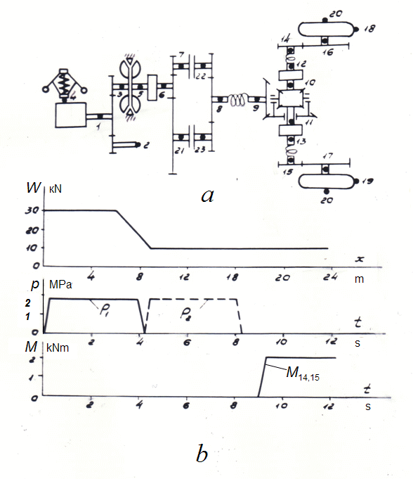
Fig. 9. The scheme of hydro mechanical transmission of self-propelled chassis
Let's consider as an example dynamics of hydro mechanical transmission (Fig. 9а) at following movement modes of the machine: 1) racing on the 1-st transfer by means of inclusion of a friction clutch 7 – 22 at resistance to moving of the machine W= – 30 kN (Fig. 9 b ); 2) transition from the 1-st transfer to the 2-nd at switching-off of a friction clutch 7 – 22 and inclusion of a friction clutch 21 – 23 with simultaneous reduction of external resistance up to W= – 10 kN (Fig. 9 b ); 3) switching-off the 2-nd transfer, movement forcefully during 0.8 s and braking up to a full stop of the machine at W= – 10 kN (Fig. 9 b ). Base parameters of the system: machine mass – 10 t; engine – diesel А -01 МД ; hydraulic torque converter with active diameter of work wheels 0.34 m; transfer numbers of a gear box : the 1-st transfer – 4.98, the 2-nd transfer – 2.75; differential: symmetric with transfer number of a gear 0.376; wheel: radius of trunks in a free condition 0.74 m; transfer numbers of a gear of selection of power: 1.183 (node 2) and 0.847 (node 3); transfer numbers of onboard gears : 5.07.
On Fig. 9
b
graphs of external influences and control signals are shown: pressures of frictional clutches control
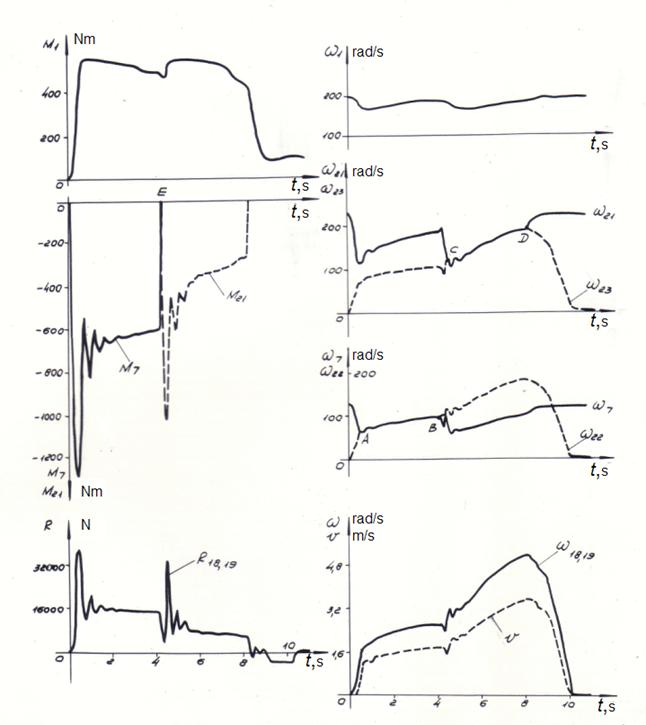
As a result of calculation the transient processes in hydro mechanical transmission have been received.
Fig. 10. Dynamics of hydro mechanical transmission (results of simulation)
On Fig. 10 graphs of variables in the certain nodes of the scheme are shown: the moments and angular speeds, and also district efforts on wheels and speed of the machine. Numbers of nodes serve for indexation of variables, for example:
|
Contents
>> Engineering Mathematics
>> Hydro Mechanical Drives and Transmissions
>> Dynamic Analysis
>> Example: simulation of dynamics of hydraulic transmission of self-propelled chassis