|
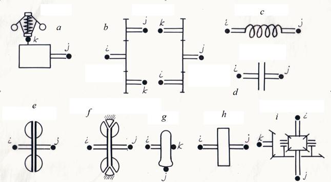
Classification of drive base elements and their nodes The analysis of various schemes of the mechanical and hydro mechanical drives applied in various mobile machines (cars, road, building, digging-transport machines, tractors, etc.), shows, that there is a final set of base elements by means of which it is possible to construct practically any mechanical or hydro mechanical drive. These elements include: a diesel engine with a centrifugal regulator, a gear, an elastic shaft, a friction clutch, a hydraulic clutch, a hydraulic torque converter, a wheel carrier, a flywheel, a differential (Fig. 1) The mathematical model of each element now is in details studied, and consequently owing to the experience which has been accumulated at simulation of various systems of a drive, the choice of the element suitable mathematical model does not represent special difficulties. Any system of a mechanical or hydro mechanical drive can be considered as set of making it elements and nodes – points of connection of these elements. Each element of the drive can be presented in the form of a three-node element with nodes i (input), j (output) and k (control or transformation of energy), connecting it with other the scheme elements (Fig. 1).
Fig. 1. Base elements of mechanical and hydro mechanical drives and their nodes. a – a diesel engine with a centrifugal regulator, b – a gear, c – an elastic shaft, d – a friction clutch, e – a hydro dynamic clutch, f – a hydraulic torque converter, g – a wheel carrier, h – a flywheel, i – a differential.
The element input and output are defined, as a rule, by the accepted direction of power stream from an engine to loading (see the table of classification of nodes). At changing of power stream direction the sign on the corresponding parameters describing work of an element varies. According to it following classification of drive base elements nodes is accepted.
Table 1. Classification of drive base elements nodes
The specified order of following of numbers of nodes is chosen from reasons of convenience of formalization of the scheme structural description which become clear of the further. Such structure description of any schemes of mechanical and hydro mechanical drives is caused by necessity of input, storage and use of input data at a so-called "element" level, differently base three-node elements with the parameters, characteristics and mathematical models are that primary information on a basis of which the algorithm of all dynamic calculation of the system is formed. According to the resulted classification each type of element has received a special name – an identifier allowing at forming of the drive general model to choose in library of mathematical models of elements the necessary group of the equations – mathematical model of an element of the given type. The following identifiers of base elements have been chosen: DIESEL, GEAR, SHAFT, FRICTION, HYCLUTCH (hydro dynamic clutch), HYTORCON (hydraulic torque converter), WHEEL, FLYWHEEL, DIFFGEAR (differential).
According to the entered identification each element
e
of drive scheme is to the certain type element with nodes corresponding it
i
,
j
,
k
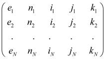
. Then the drive any scheme structure after numbering of its all nodes can be described by the following
matrix of communications
where e 1 , …. , e N – elements, N – their number, n – an element type serial number. The identifier e m defines the mathematical model corresponding an element, numbers of nodes i m , j m , k m serve for indexation of variables and, as consequence forming of communication conditions of elements with each other. For example, if the output of an element e m is at the same time an input of an element e l it is obvious, that j m = i l , and therefore, variables on an output e m and on an input e l coincide, i.e. the corresponding condition of communication takes place; the serial number n of an element type serves for convenience of mathematical model forming.
As a result of scheme structure such description those equations will be chosen from the general library of mathematical models of elements by which the elements entering into the scheme are described, and indexation of the variables entering into the equations (conditions of communications), will be established on a basis of numbering nodes of the elements specified in a matrix
Thus, the description of structure (topology) of any arbitrary scheme of a mechanical and hydro mechanical drive for the dynamic analysis is formalized by: - drawings on the working scheme of nodes – points of connection of elements and numbering of nodes;
- forming of a structural matrix
|
Contents
>> Engineering Mathematics
>> Hydro Mechanical Drives and Transmissions
>> Dynamic Analysis
>> Structure description of arbitrary hydro mechanical circuits
>> Classification of drive base elements and their nodes