|
Algorithms of forming and solving of the drive mathematical model Forming of input data. All input information for executing of dynamic analysis of mechanical and hydro mechanical drives consists of two parts: - the information on structure of the considered drive scheme; - the information about physical and design data of the drive scheme elements. The first part of the input information is under construction according to the method of the structural description of the arbitrary hydro mechanical schemes, stated above, based on classification of base elements of a drive , introduction of concept of the generalized three-unit element with units i (input), j (output) and k (a control, an energy transformation, a supply or selection of power). On a basis of the entered classification (tab. 1) each element of a drive has received the certain identifier е , designating type of an element and unequivocally defining group of equations for the mathematical description of the given type element. According to it special forms (tables) of input data have been developed. Each typical element of a drive is described by the line of the table of input data having following structure:
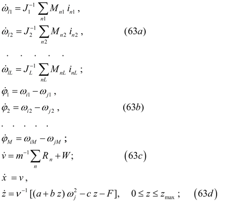
where n – number of an element; A – a matrix-line of coefficients describing physical, geometrical and design data of an element, that is the contents of the second part of input information. At the elements having only two units (for example, a diesel engine, frictional and hydro dynamical clutches, an elastic shaft, a flywheel) the third unit is designated by zero. Number of an element n is intended for a choice of the necessary file of factors from the general field of input data at forming of the system of equations. Forming of the drive scheme mathematical model as a whole. As a result of the analysis of a line of the table of the each element input data and the structural analysis of the scheme with its fragmentation into sites the system of the differential equations of dynamics of the hydro mechanical drive, having generally following structure, is formed:
where the first L equations (63 а ) – equations of dynamics of L sites of the scheme to which at presence wheel carrier the equation of one more site – the equation of the machine forward motion (63 c ) is added; the M of the equations (63 b ) are necessary for definition of torque angles of a elastic shaft (at their presence in the scheme), and at last, the last equations (63 d ) describe the machine forward motion and dynamics of a centrifugal regulator of a diesel engine. The algorithm of forming the system of equations (63) is reduced to the following.
At the first stage
the equations of sites (63
а
and
d
) are formed. For this purpose values of the resulted moments of inertia
At the second stage the equations (63 b ), which number is equal to number of elastic shafts in the drive scheme, and the equations (63 d ) of movements of the machine and a diesel engine regulator muff are formed. External influences and control signals. The information on external fluencies and control signals is given in specially developed table of input data (Fig. 8).
Fig. 8. Information about external influences and control signals
Here various types of external influences are stipulated: a friction clutch control, a hydraulic torque converter, influence of a road profile to a wheel (axis), braking torques, external torques, resistance to machine moving, control of a pedal of gas (fuel feed in the diesel engine). For each given type of influence there is specified either number of an element, or number of unit in which the given influence operates, and also the way of the task of this and influence: in the form of function
у
(
х
), given in the form of table and approximated by a finite set of discrete values
Algorithm of solution. For integration of systems of the differential equations now there is a huge set of methods of numerical integration (Runge-Kutta, Euler’s methods and their updating ones, Gear's method, etc.) on a basis of which a majority of various updating methods and corresponding programs are developed, that allows always to choose the suitable instrument of solution. |
Contents
>> Engineering Mathematics
>> Hydro Mechanical Drives and Transmissions
>> Dynamic Analysis
>> Algorithms of forming and solving of drive mathematical model