|
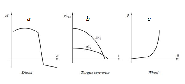
System of the equations Calculation of traction characteristics of hydro mechanical transmission of wheel machine is reduced to the solution of the following system of nonlinear equations (1) considering the external characteristic of diesel engine with centrifugal regulator (Fig. 2 а ), the characteristic of hydraulic torque converter (Fig. 2 b ) and the slipping characteristic of wheel mover (Fig. 2 c ) [1]:
Fig. 2. Characteristics of elements of hydro mechanical transmission
where a, b, k r – constant adjustments of a regulator of a diesel engine; c, F – rigidity and force of a preliminary compression of regulator spring; z max – the maximal displacement of regulator moving muff; M ( ω e ) – the diesel engine characteristic at the minimal fuel consumption; M z – an increment of the torque moment at the maximal fuel consumption; M ( ω e ) + M z - the diesel engine external characteristic (Fig. 2 a ); u e – transfer ratio of matching gear; ρλ 1,2 ( i ) – characteristics of hydraulic torque converter (Fig. 2 b ); D – active diameter of pump and turbine wheels of hydraulic torque converter; k п , М о – coefficient and constant value of engine torque losses; R – circle force to wheels; r w – radius of wheel rolling ; u mech – transfer ratio of bridge gear; η mech – mechanical efficiency of bridge gear; Т – traction force; G – machine weight; φ – coefficient of the wheel rolling resistance. Unknowns of equations (1) are: z – displacement of regulator moving muff; ω e – angular speed of the engine shaft; М s – the engine shaft torque moment; ω p , ω t – angular speeds accordingly a pump and turbine wheels of hydraulic torque converter; М t – the torque moment on the hydraulic torque converter turbine wheel shaft; i – the transfer relation of hydraulic torque converter; v – speed of the machine movement; δ – relative slipping of wheels, δ =f ( R ) – the slipping characteristic of wheel mover (Fig. 2 c ). |
Contents
>> Engineering Mathematics
>> Mobile Machines
>> Traction Analysis
>> One engine transmission
>> System of equations