|
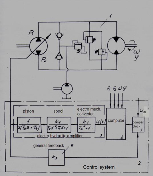
Examples E x a m p l e 1. Control system of a hydraulic drive on the basis of typical linear links of ACS. On Fig. 2 the hydraulic drive circuit with a control system described by a set of typical linear links of automatic control is presented.
Fig. 2. Control system of a hydraulic drive on the basis of typical linear links of ACS
Object of control – hydraulic system 1 with the closed contour of circulation of a working fluid. The control system 2 consists of the electro hydraulic amplifier (EHA) 3 , a computer 4 , the block of comparison 5 and the general feedback 6 .
The electro hydraulic amplifier
3
is presented as consecutive connection of typical linear dynamic links: a conservative link
7
(the electro mechanical converter), the 2-nd order aperiodic link
8
(a spool of the hydraulic amplifier) and an inertial integrating link
9
(the piston of the hydraulic amplifier).
In a feedback 6 there is an intensifying link. The block of comparison
5
is the summer. Concrete realization of a computer 4 depends on algorithm of transformations carried out by it. Designations on Fig. 2:
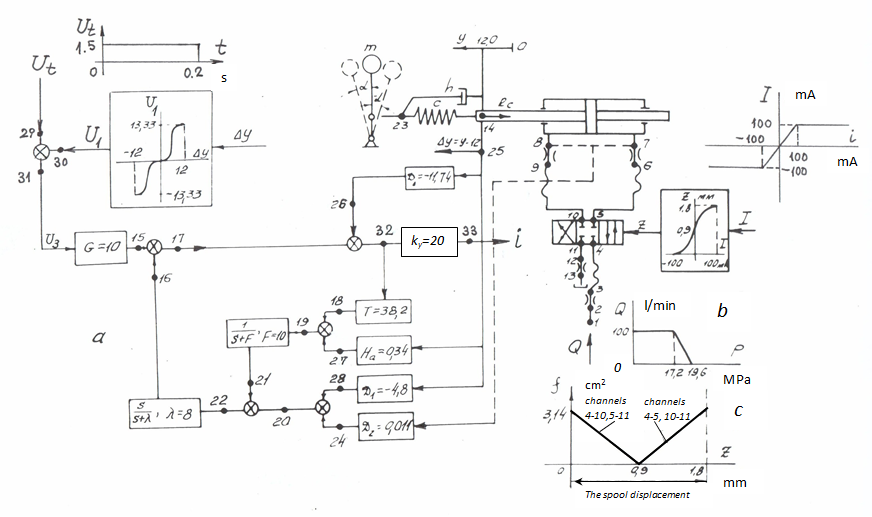
E x a m p l e 2. Simulation of a control system by a hydraulic drive. Let's consider a problem of simulation of dynamics of a hydraulic drive of the testing stand with an electro mechanical control system (Fig. 3).
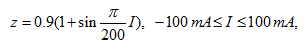
Fig. 3. The circuit diagram of a hydraulic drive of the testing stand with an electro mechanical control system The hydraulic drive of the stand consists of the hydraulic cylinder (7–8–14), moving the lever mechanism (14-23) with cargo in a mass m , having a rigidity c and damping properties h and has been described by the 2-nd order aperiodic link; directional spool valve (4–5–10–11); pipelines (1–2) and (11–12); hoses of high pressure (3–4), 5–6) and (9–10); throttles (2–3), (6–7), (8–9) and (12–13); electro mechanical control system, consisting from 15 linear dynamic links: amplifiers (31-15), (25-26), (32-33), (32-18), (25-27), (25-28), (7-8-24), an inertial differentiating link (22–16), the 1-st order aperiodic link (19–21), adders (15–17–16), (20–22–21), (27–19–18), (24–20–28), (29-31-30), (26–32–17); and two nonlinear links: electro mechanical converter z ( I ) of the following form:
where z is a spool position, I – a current;
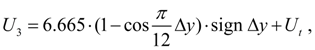
and the entrance signal
where
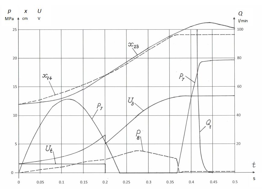
Thus, the system consists of 29 elements connected in 36 nodes, and is described by the 40-th order system of algebraic-differential equations. Basic parameters of hydraulic system: hydraulic cylinder: the piston diameter 100 mm, the rod diameter 45 mm, the piston stroke 240 mm; pipelines and hoses of high pressure: diameter 22 mm, lengths: (1–2) – 6 m, (3–4) – 5.34 m, (5–6) –0.69 m, (9–10) – 0.64 m, (11–12) – 11.3 m; throttles: sectional areas: (2–3) – 3.8 sm², (6–7) – 3.14 sm², (8–9) – 3.14 sm², (12–13) – 1.17 sm², resistance coefficients: (2–3) –5.54, (6–7) –3.28, (8–9) –3.28 и (12–13) –11.38; directional spool valve: diameter of conditional passage 20 mm, a spool stroke 1.8 mm, flow coefficient of spool channels 0.62; geometric characteristics of spool channels, expressing dependence of sectional areas of channels on spool position z , is presented on Fig. 3 c . working fluid: density 850 kg/m 3 , kinetic viscosity 2 . 10 -5 m 2 /s, the volumetric elasticity module 1765 MPa; mechanism : mass m = 19600 kg, rigidity c = 6.86 . 10 6 N/m, coefficient of viscous friction h = 0. Force on the rod R c = c ( x 14 – x 23 ) . Dependence of the flow Q 1 in node 1 (Fig. 3 b ) considers the static characteristic of pressure relief valve not shown on the circuit diagram. Coefficients of equations of dynamic links are specified Fig. 3 а . Transient processes in a hydraulic drive of the testing stand, received as a result of mathematical simulation, are presented on Fig. 4.
Fig. 4. Dynamics of a hydraulic drive of the testing stand with an electro mechanical control system Similar calculations and researches executed on a design stage, allow to find an optimum variant of a control system for concrete object of control, for example, for a hydraulic drive. |
Contents
>> Engineering Mathematics
>> Control Systems
>> Dynamic Analysis of Control System of Hydraulic Drive
>> Examples