|
Traction-dynamic analysis of hydro mechanical transmissions
The wide nomenclature of jib self-propelled cranes in a range of lift capacities from 25 up to 400 tons requires for their completion of
a plenty of models of diesel engines.
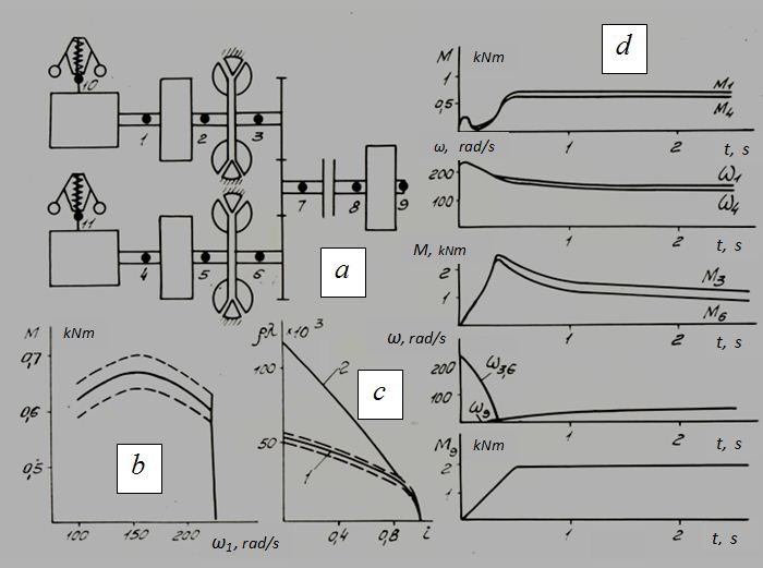
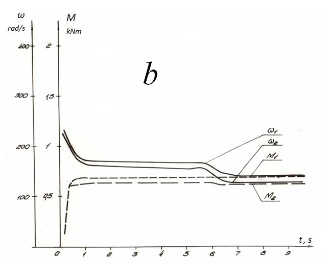
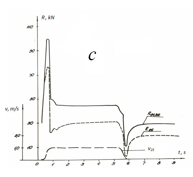
Fig. 1. The rated diagram (Fig. 1, a ) included two engines, two hydraulic torque converters, the general gearbox with the reduced load on its outlet axle. Such rated model allowed estimating:– a fuel profitability and a stock of power of engines at the maximal resistance to movement of the machine, – an efficiency of hydraulic torque converters and duration of their work in a stop mode, – a degree of circulation of power in the power modules of transmission. Rated oscillograms of transients in the power modules, arising at dispersal are resulted as an example on Fig. 1. Characteristics of engines (dependence of rotating moments on angular speeds) differ on 10% (Fig. 1, b ). The same order mismatch has been given in characteristics of hydraulic torque converters (Fig. 1, c ). Thus real conditions, in which actual characteristics of engines and hydraulic torque converters (dotted curves on Fig. 1) can differ from passport (continuous lines in the same place) on 5 % in this or that side were simulated. It can bring to the power circulation effect in power modules, as was observed, the truth, in an insignificant degree. However at such statement of a problem it is impossible to estimate the effects connected with dynamics wheel propelling and elastic elements of transmission at dispersal and braking. At the same time traction-dynamic calculation of hydro mechanical transmissions is a necessary stage of creation of cranes on the chassis of the raised passableness. With this objective rated diagrams of hydro mechanical transmissions of cranes KS-63 (Fig. 2) and KS-100 (Fig. 3), containing besides power-plants (Fig. 1, a ) such elements, as elastic shafts, differentials, tires have been considered. In view of the specified characteristics (of frictional clutches, elastic properties of shaft, slipping of wheels, etc.) have been received fuller and more authentic dispersal characteristics of hydro mechanical transmissions of cranes at various road conditions.
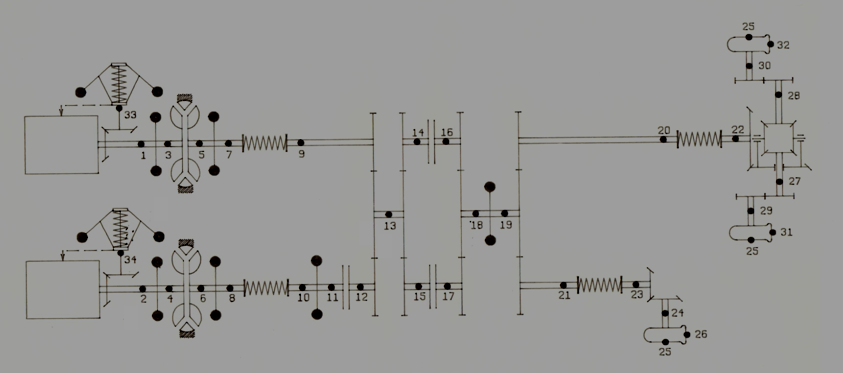
Fig. 2.
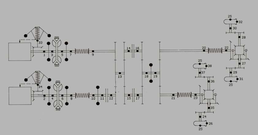
Fig. 3. Each of the rated circuit diagrams according to requirements of the program DRIVE is presented in the form of set of elements and connecting nodes and contains two diesel engines with centrifugal regulators (nodes 1-33 and 2-34), two hydraulic torque converters (nodes 3-5, 4-6), a gearbox (nodes 9-12-13-14-15-16-17-18-19-20-21), summarizing both of power streams, which outlet shafts (nodes 20 and 21) are connected through elastic shafts with wheel bridges. In the diagram of hydro mechanical transmission of crane KS-63 (the wheel formula 8х6) one interbridge differential (nodes 22-27-28) is available; in the diagram of hydro mechanical transmission of crane KS-100 (the wheel formula 10х8) two interbridge differentials (with nodes 22-27-28 and 23-35-36) are available. Each wheel bridge is represented on the diagrams in the form of an equivalent wheel with the double parameters (a moment of inertia, circular effort, rigidity, etc.).Work of hydro mechanical transmission on I (V) transfer was simulated by inclusion of a friction clutch 15-17, on II (VI) transfer – inclusion of a friction clutch 14-16. Work of hydro mechanical transmission on different transfers (I and V, II and VI, etc.) was defined by the assignment of various transfer numbers of reducers of the gearbox. Total of elements in the rated diagrams of hydro mechanical transmissions: 28 for crane KS-63, 31 – for crane KS-100. The order of mathematical model is accordingly 22 and 24.
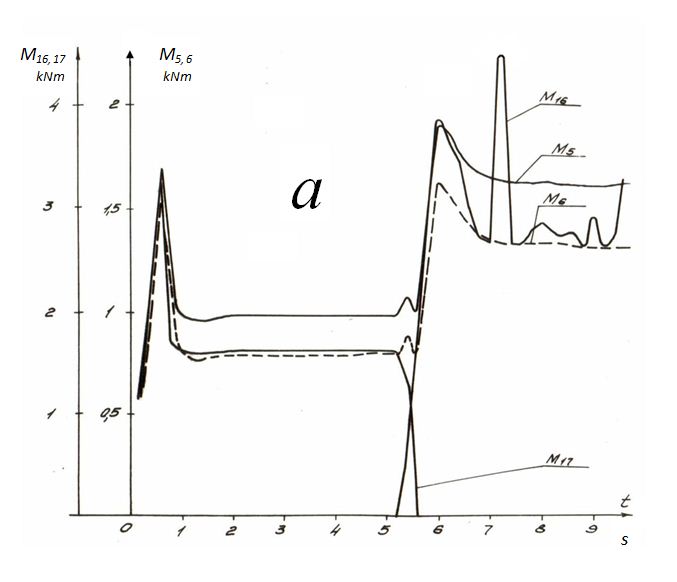
Fig. 4. As an example the rated oscillograms of transients in hydro mechanical transmission of crane KSH-63 at dispersal on I transfer and switching to II transfer are resulted on Fig. 4. Here it is designated: t – time, s; M – a moment, kN· m; ω – an angular speed, rad/s; v – speed of forward motion of the crane, m/s; R – a "wheel" (the wheel bridge) circular effort, kN; W – a road resistance, kN. As well as earlier, the index at a variable means number of node on the rated diagram in which this variable operates ( ω 1 – an angular speed in node 1, М 16 – a moment in node 16, etc.).Simulated dynamics of hydro mechanical transmission at dispersal on a wet ground on I to transfer on a bias 8°, with the subsequent switching to II transfer with overlapping on time 0.2 s (there is in view of an interval of time when the friction clutch I of transfer 15-17 will not open yet completely, and the friction clutch II of transfer 14-16 has already started to become isolated). It is possible to observe this effect on Fig. 4, a on a relative positioning of dependences of moment М 17 ( t ) of friction clutch 15-17 and moment М 16 ( t ) of friction clutch 14-16. As can be seen from Fig. 4, a , b , dispersal on I transfer at the specified road conditions lasts approximately 1.5 – 2 s and is characterized by peak values of moments М 17 , М 5 and М 6 at t ≈ 0.6 s. However these processes quickly fade and by the time t = 2 s about all phase variables become practically constants – there comes a stationary mode of movement on I transfer. At switching on II transfer dynamics of phase variables is observed again. Especially obviously it is shown at a moment of a friction clutch of II transfer ( М 16 ) and moments of turbine wheels of hydraulic torque converters ( М 5 and М 6 ). At the same time dynamics of moments on diesel engines shafts ( М 1 and М 2 ) is insignificant and carries almost aperiodic character with fast transition in statics. Transients of variation of circular traction efforts R 26 , R 31 , R 32 have similar character. It is clearly visible, that at switching on II transfer there is a stop of the crane (speed v 25 reduces to zero), because total traction effort R 26 + R 31 + R 32 = 80 kN becomes insufficient for overcoming total resistance W ≈ 120 kN (movement resistance makes ~52 kN, resistance from a bias 8° is approximately equal 68 kN). It is necessary to note, that as a result of non-uniform weight distribution on axes traction efforts of wheel bridges R 26 , R 31 , R 32 essentially differ (in a stationary mode in ~1.5 times). On each machine the set of such calculations in which the values has been varied: switching of transfers, a bias of road, a type of a road covering, overlapping on time of inclusion-shutdown of friction clutches of gearbox, as well as deviations of «actual» characteristics of a diesel engine and a pump wheel of the hydraulic torque converter from their passport characteristics in that and other side (up to 5%), and a deviation of characteristics of a diesel engine and the appropriating hydraulic torque converter were taken with different signs. The executed on mathematical models analysis of two-modular system of a drive in view of 5% deviations from nominal characteristics of diesel engines and hydraulic torque converters, elastic properties of elements of transmission, tires, various factors of grip of the weel, various time of overlapping of friction clutches of gearbox, in conditions of movement on limiting biases and dispersal on horizontal sites of roads, at association of streams of power of two power modules has shown: – the two-motor system of a drive of the cranes 63 and 100 t (with the wheel formulae accordingly 8х6 and 10х8) provides with carrying power takeoff and dispersal of crane on I transfer at extreme conditions of movement (rising on a wet ground at a bias 8°); – switching in these conditions on II transfer leads to latching of turbine wheels of hydraulic torque converters and proslipping of friction clutches with transition to a reversible mode owing to shortage of installed power; diesel engines thus work in a mode close to flameout; – at movement on dry asphalt on a horizontal site of road dispersal of the crane on V transfer and switching on VI – the accelerated transfer are provided that testifies to high dynamic qualities of the drive; however speeds of movement of cranes KS-63 and KS -100 at transition from V transfer to VI transfer change differently: the crane KS-63 speed practically does not change, and the crane KS-100 speed increases in 1.5 times that speaks a different level of specific power and work on various working zones of external characteristics of hydraulic torque converters. The analysis of dynamic loads in elements of transmission has allowed establishing an optimum value of overlapping on time of inclusion of friction clutches of gearbox. For cranes KS-63 and KS -100 it makes 0.3 s. Transients on circular efforts of wheels and moments of pump wheels of hydraulic torque converters in this case become aperiodic, while for other values of overlapping (0.1, 0.2, 0.4 s) oscillatory processes with significant amplitudes take place. The comparative analysis of traditional single-motor system of a drive with the two-modular circuit diagram has shown, that fuel profitability of the last a little bit above. So, in the established mode on I transfer the difference in values of specific fuel consumption makes 5-9%. Carrying out of such calculations provides the foundation for the alternative analysis necessary at creation of new drives and transmissions, for example, with two modular structure of a drive, and allows estimating correctness schematic decisions at design of hydro mechanical transmission, to choose its basic elements and to develop on this basis specific requirements to a control system. |
Contents
>> Analysis and Design
>> Systems of Hydro Mechanical Drives
>> Hydro Mechanical Transmissions of the Jib Self-Propelled Cranes
>> Traction-dynamic analysis of hydro mechanical transmissions of the jib self-propelled cranes KS-63 and KS-100