|
Dynamics of the main hydraulic drive of the auto concrete pump SB-126
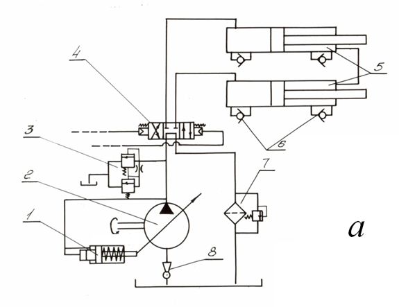
Fig. 1. The basic ( a ) and the rated ( b ) diagram of the main hydraulic drive of the auto concrete pump SB-126. On the basic diagram of the main hydraulic drive of auto concrete pump SB-126 (Fig. 1, a ) there are designated: 1 - the power regulator 400.32, 2 – the pump of variable displacement 207.32, 3 – the pilot operation pressure relief valve 510.32, 4 – the hydraulic directional valve R323, 5 – the hydraulic cylinders 100х63х1400, 6 – the return valves 4121.20, 7 - a filter, 8 – an ejector. As at calculation one cycle of work of hydraulic cylinders of the main drive was considered only, elements of the valve and distributive apparatuses have not been included in the rated diagram, providing switching of hydraulic cylinders from a suction step to a concrete injection step [1, 4].Thus, the rated diagram of the main hydraulic drive of the auto concrete pump SB-126 (Fig. 1, b ) consists of the pump of variable displacement 207.32 with the power regulator 400.32 (a capacity of ~51.5 kW, an adjustment pressure of ~13 MPa), two hydraulic cylinders 100х63х1400, the pilot operation pressure relief valve 510.32 which have been adjusted on a pressure ~20.6 MPa, connected by hydraulic lines. The site of the hydraulic line connecting the pump with the hydraulic cylinder consists of a sleeve of a high pressure (diameter of nominal bore of 32 mm, length 1.65 m) and the steel pipeline (diameter of nominal bore of 40 mm, length 1.2 m). Throttles 4-5 and 10-11 simulate losses of pressure in local resistance on the actual diagram (Fig. 1, a ). Parameters of a working liquid: density of 900 kg/m 3 , kinematic viscosity 3·10 –5 m 2 /s, the volumetric module of elasticity 980 MPa. The crosspiece of hydraulic cylinders on the basic diagram represents a short site of pipeline; therefore it is replaced on the rated diagram by equivalent local resistance (the throttle 6-8). According to the algorithm of forming of mathematical models of the hydraulic drives , accepted to the program of the computer-aided dynamic analysis of hydraulic systems (HYDRA), nodes – points of connection of hydraulic elements in the diagram are put and numbered on the rated diagram. Then the rated diagram of the main hydraulic drive of the auto concrete pump SB-126 consists of 13 hydraulic elements connected in 21 nodes, and is described according to structure of hydraulic elements and their mathematical models by system of differential and transcendental equations of the 36-th order.
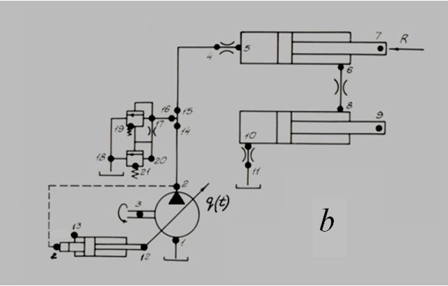
Fig. 2. The load from a column of the concrete mixture, acting on the concrete mixture cylinders pistons, rigidly connected by the general rods with pistons of hydraulic cylinders, is set by two components: variable force in function of the hydraulic cylinder piston movement z , simulating process of compression of a mixture in view of incomplete filling of the concrete mixture cylinders and process of its movement with the certain resistance (Fig. 2, a ), and the variable mass reduced to the hydraulic cylinder rod (Fig. 2, b ), equal to sum of masses of the hydraulic cylinder piston with a rod and the concrete mixture cylinder piston on an initial piece of movement ( z ≤ 0.35 m, Fig. 2, b ) and undergoing a jump at z = 0.35 m in view of addition of mass of a column of a concrete mixture. Clearly, that such model of a load does not consider possible fluctuations of pressure in a concrete mixture. However, the account of this component becomes possible only after carrying out of appropriating experiments with objective of studying of character of wave and oscillatory processes in a concrete pipeline.For modeling of emergency operation of stopping of the hydraulic cylinder at sharp increase of a load (and studying of dynamics of hydraulic system at operation of a pressure relief valve) in addition to dependence (Fig. 2, a ) a case of sharp jump of a load (Fig. 2, c ) at z ≥ 0.7 m has been considered. The dynamic analysis of working processes in the main hydraulic drive of the auto concrete pump SB-126 was spent for the following modes: 1) a horizontal position of a boom at a rated load of movement resistance; 2) a horizontal position of a boom at a jump of load up to maximal (stopping of the hydraulic cylinder) at: a) the disconnected power regulator, b) the connected power regulator; 3) a vertical position of a boom at a nominal and maximal load. As a result of calculation of transients on a pressure р 5 in the hydraulic cylinder (node 5 in the rated diagram, Fig. 1, b ), a speed v 7 and a movement z 7 of the hydraulic cylinder rod (node 7, Fig. 1, b ), a movement z 12 of plunger of a power regulator (node 12, Fig. 1, b ) in function of time t have been received.
Mode of nominal loads at horizontal position of a boom
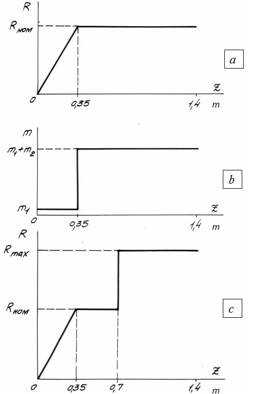
Fig. 3. For this mode enough smooth variation of pressure р 5 , despite of spasmodic variation of the reduced mass which affects only own frequency of fluctuations changing too unevenly at z 7 = 0.35 m from 30 Hz up to 11.4 Hz is characteristic. As at the set load pressure р 5 does not reach the adjustment pressure of a power regulator (~13 MPa), the last does not put into operation.
Mode of maximal loads at horizontal position of a boom
The diagram without the power regulator
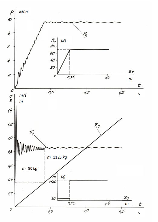
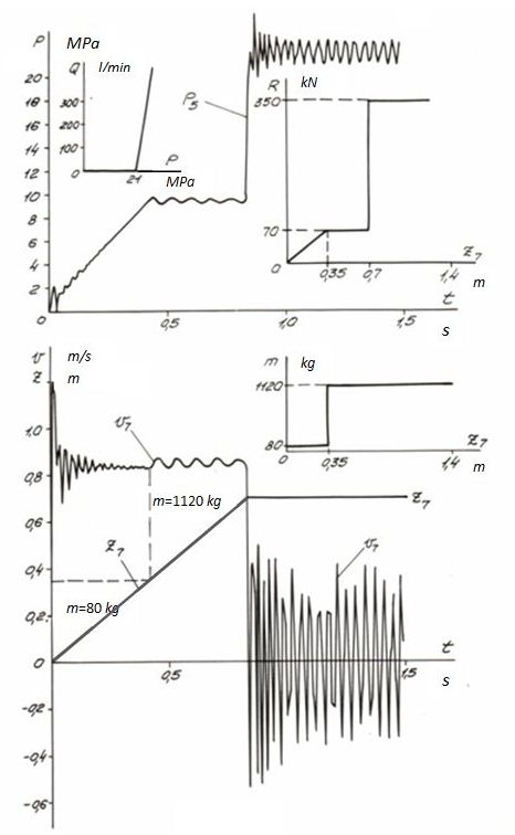
Fig. 4. On Fig. 4 transients in the auto concrete pump hydraulic drive are presented at the disconnected power regulator. At 0 ≤ z 7 ≤ 0.7 m in the system rated loads operate; at z 7 > 0.7 m the load on rod R 7 changes unevenly from 68.6 kN up to 343 kN (simulating an absolute obstacle). Pressure р 5 increases thus up to value of pressure relief valve adjustment which work is modeled by its static characteristic Q ( p ).
The diagram with the power regulator
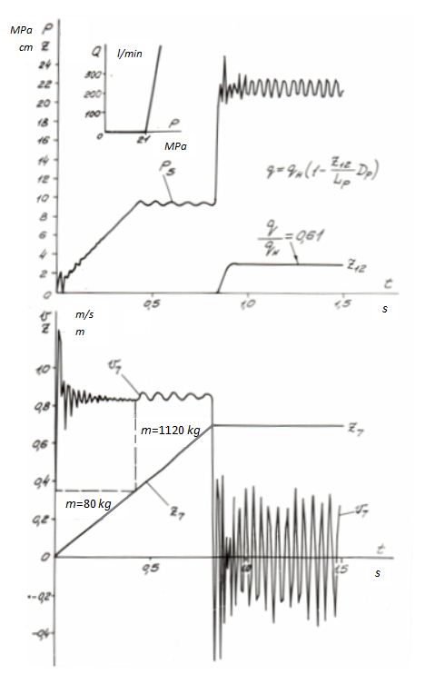
Fig. 5. On Fig. 5 transients in the auto concrete pump hydraulic drive are presented at connection of the power regulator. As well as in the previous case, at 0 ≤ z 7 ≤ 0.7 m in the system rated loads operate; at z 7 > 0.7 m the load on rod R 7 changes unevenly from 68.6 kN up to 343 kN. In this case at sharp increase of pressure р 5 alongside with the pressure relief valve the power regulator works also (a curve z 12 of the regulator plunger movement on Fig. 5), reducing geometric volume of the pump up to ~0.61 from maximal. However, apparently from graphs Fig. 5, it does not bring sufficient variations in dynamics of the drive in view of operation of the pressure relief valve which in this case passes on drain a smaller stream (on the average ~250 l/min instead of 405 l/min at absence of the power regulator), that affects only decrease in average value of pressure р 5 .
Mode of nominal and maximal loads at vertical position of a boom
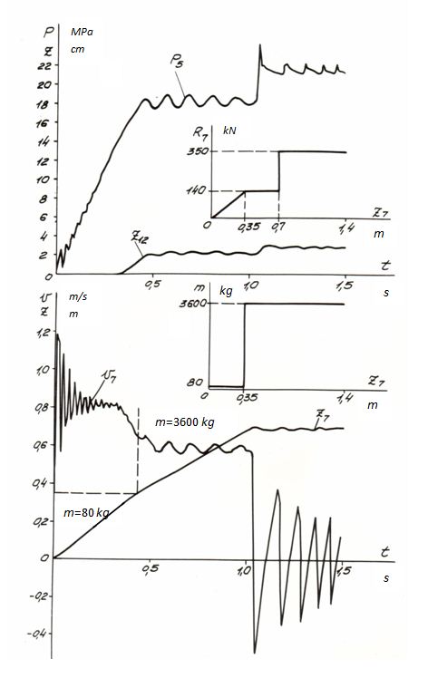
Fig. 6. Graphs of transients for this mode (Fig. 6) show, that the power regulator (the curve z 12 ) in this case works at a nominal load, as a level of nominal pressure р 5 above, than in the previous cases. Therefore even before increase of load R 7 up to maximal (stopping of the hydraulic cylinder) decrease in speed of the piston v 7 is observed at р 5 > 13 MPa. Besides displacement of a frequency range and amplitude of fluctuations is observed in view of the greater reduced mass of the hydraulic cylinder piston.
Mode of nominal loads at vertical position of a boom and
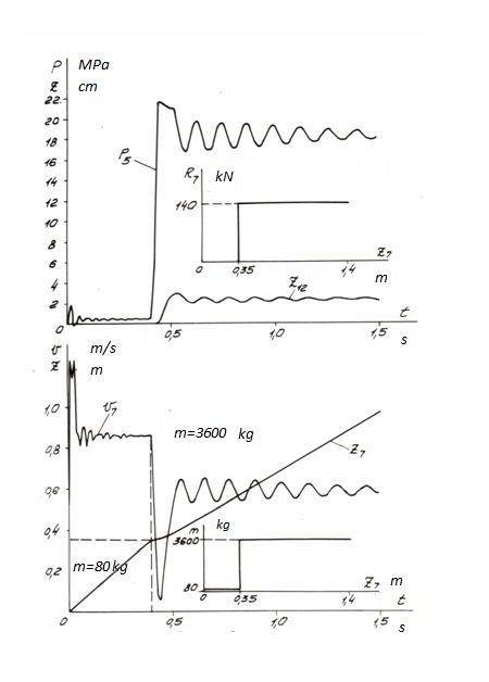
Fig. 7. Results of dynamic calculation for this version are presented on Fig. 7. Characteristic instant is raised on comparison with the previous case (about twice) amplitude of fluctuations of pressure р 5 , speeds v 7 and movement z 12 of the regulator plunger and sharp falling (almost up to zero) of a rod speed v 7 at operation of a pressure relief valve (at 0.4 s < t < 0.44 s, Fig. 7). In process of pressure decrease and closing of the valve there is a restoration of a rod movement, but to smaller speed in view of operation of a power regulator. In the same place, on Fig. 7, the dependence R 7 ( z 7 ) for this rated case is resulted.Carried out researches have allowed to specify a necessary level of adjustment pressure of the power regulator, to reveal influence of character and sizes of external loads on qualitative and quantity factors of transients (amplitudes and frequencies of fluctuations, peak pressures) to define dynamic characteristics of the power regulator. |
Contents
>> Analysis and Design
>> Systems of Hydraulic Drives
>> Hydraulic Drives of Auto Concrete Pumps
>> Dynamics of the main hydraulic drive of the auto concrete pump SB-126