|
Dynamics of a hydraulic drive of the turn mechanism of the auto concrete pump BR-14
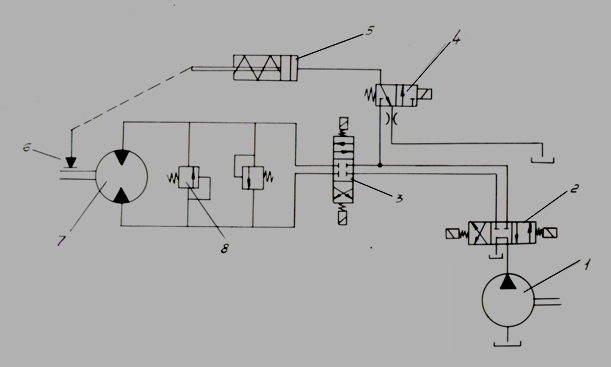
Fig. 1. On Fig. 1 the basic circuit diagram of a hydraulic drive of the turn mechanism of the auto concrete pump BR-14 is presented. Supply of a working liquid to the hydraulic motor 7 is carried out by the pump 1 at simultaneous inclusion of spools 2, 3 and 4, moved by means of electromagnets. At inclusion of the spool 4 piston of the hydraulic breaker 5 moves and there is a disconnection of the block brake 6. At inclusion of electromagnets spools (including 4) and the piston of the hydraulic breaker come back by action of springs in original position, the brake locking occurs.For protection of hydraulic system from excessive high pressures in the circuit diagram the pilot operated pressure relief valves 8 are stipulated. The throttle established in a drain hydro line on an output of the spool 4, provides a delay in the brake operation, as it is of lay type. The last circumstance, as well as existing initial open-circuit at shorting of the brake allows to consider, that braking of the turn mechanism is carried out by purely hydraulic way, that is at switching spool 3 to a neutral position a cutoff of a working liquid from the pump occurs; the hydraulic motor, rotating by inertia, passes in so-called «a pump mode», forcing a liquid in a cut off volume of the drain hydro line. Pressure in this cavity raises and there is the hydraulic motor braking. At dispersal of the turn mechanism the brake in an initial stage will be closed, therefore it is necessary to consider influence of the brake moment on the hydraulic motor shaft at dispersal. For decision of the posed problem the universal program of dynamic analysis of hydraulic systems of any structure HYDRA was used.
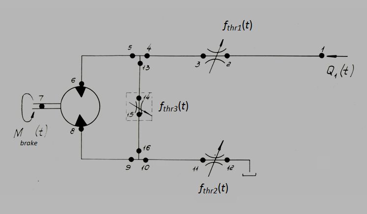
Fig. 2. The simplified circuit diagram (Fig. 2) contains of 13 elements connected in 16 nodes. The resulted simplified hydraulic diagram differs from the basic diagram by number of simplifications: some hydraulic elements are replaced by their appropriating functional characteristics. Flow Q 1 ( t ), operating in node 1, simulates the pump supply in hydraulic system by means of an operating spool (poses. 1 and 2, Fig. 1); by means of throttles of variable through passage section f thr1 ( t ) and f thr2 ( t ) modeling process of inclusion of the basic directional spool valve of the hydraulic drive of the turn mechanism (pose 3, Fig. 1), and the throttle f thr3 ( t ) simulates work of pressure relief valve (pose 8, Fig. 1) by its static characteristic Q ( p 14 – p 15 ), that is dependence of flow in node 14 from the pressure differential in nodes 14 and 15. The moment on the hydraulic motor shaft of M brake ( t ) in node 7 models the brake action.Let's consider the characteristics of external perturbations presented on Fig. 3.
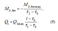
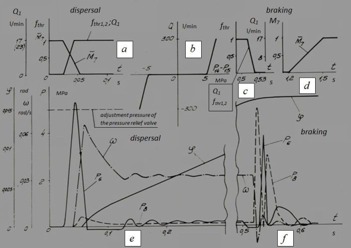
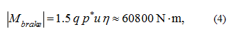
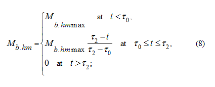
Fig. 3. According to passport data of the directional control valve VE10.44 (pose 3, Fig. 18) the value of overlapping is 1.3 mm at a course from a neutral position to the working one of 3.2 mm. Thus, the insensibility zone for this directional control valve makes ~40% from the general course of a spool in one side. Proceeding from geometry of the directional control valve, the maximal area of through passage section of the channel is reached at moving a spool on 1 mm from the beginning of opening of the channel. In view of that time of inclusion of a spool makes ~0.06 s, and shutdowns ~0.04 s (the passport data), as well as considering geometrical symmetry of the directional control valve, we shall receive (Fig. 3, a , c ) dependences of functions of through passage sections of throttles f thr1 and f thr2 , simulating channels of the directional control valve (pose 3, Fig. 1).According to the resulted data at inclusion of the spool its insensibility zone on time makes ~0.024 s, and regulation zone ~0.019 s. At shutdown of the spool the same temporary intervals are less in 1.5 times. Similar dependence (Fig. 3, a ) is accepted for a flow Q 1 ( t ), simulating the pump supply through the directional control valve (pose 2, Fig. 1). The static characteristic of pressure relief valve Q ( p 14 – p 15 ) is resulted in the graph form on Fig. 3, b . This dependence is included into the equation for definition f thr3 – functions of through passage section of the throttle connecting nodes 14 and 15, and considers a possibility of change of a sign on flow (the pressure differential). That one dependence describes both of the pressure relief valves of hydraulic system. If to accept, that geometrical characteristics and speed of the directional control valves 3 and 4 (Fig. 1) coincide, without taking into account delay of a signal in a hydraulic path of a hydraulic breaker of a brake it is possible to consider, that variation of a relative brake moment
where q = 17.03·10 –6 m 3 / rad – geometric volume of the hydraulic motor 210.25; р * = 4.9 MPa – the adjustment pressure of the pressure relief valve; u = 513 – transfer number of the turn mechanism; η = 0.945 – hydraulic-and-mechanical efficiency of the hydraulic motor. Then the actual brake moment is equal:
where
ω
7
– an angular speed of the hydraulic motor shaft.
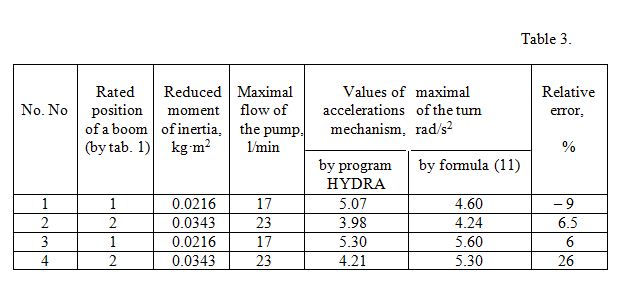
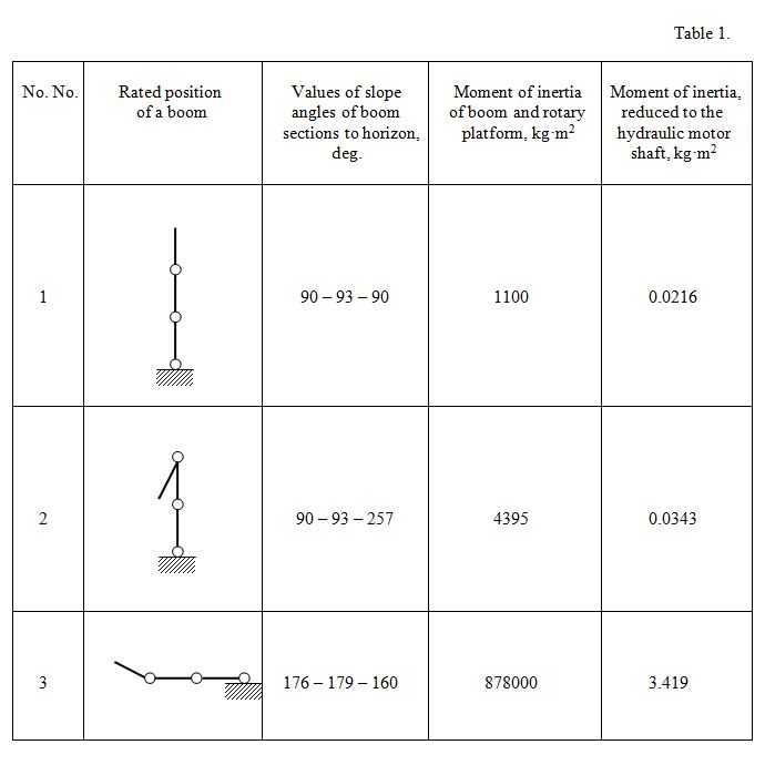
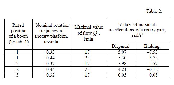
Other parameters of hydraulic elements are taken from their passport characteristics and the geometrical sizes. In tab. 2 values of maximal angular accelerations of the auto concrete pump BR-14 rotary part are resulted at dispersal and braking for three accepted rated positions of boom (tab. 1) and two values of nominal rotation frequency of rotary platform (two maximal values of flow Q 1 ), received as a result of calculations of dynamics of the turn mechanism hydraulic drive by the program HYDRA.
The example of the rated oscillogram illustrating dynamics of the turn mechanism hydraulic drive for the 1-st rated position
of a boom is resulted on Fig. 3,
e
,
f
. Here it is designated:
р
6
,
р
8
– pressures accordingly in nodes 6 and 8 (see the rated diagram Fig. 1),
ω
,
φ
– angular speed and angle of turn
of a platform.
Dispersal
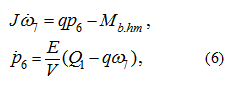
1) pressure in hydraulic system does not reach a level of the adjustment pressure of the pressure relief valve; 2) losses of pressure on length, in local resistance, losses of a moment on friction in the hydraulic motor, outflow of a working liquid are insignificant also it is possible to neglect them; 3) pressure in a drain hydro line of hydraulic motor negligible and maybe is accepted equal to zero. It is according to the accepted assumptions the simplified mathematical model describing dynamics of a hydraulic drive of the turn mechanism, looks like:
where
J
– a moment of inertia of rotating parts of the turn mechanism reduced to the hydraulic motor shaft;
q
– a geometric volume of the hydraulic motor;
М
b.hm
– a brake moment reduced to the hydraulic motor
shaft;
Е
– an equivalent volumetric module of elasticity of pipelines and sleeves of a high pressure with a liquid;
V
– a volume of pipelines and sleeves of a high pressure in a pressure piping;
ω
7
– an angular speed
of the hydraulic motor shaft (node 7, Fig. 2),
р
6
– a pressure upon an input in the hydraulic motor (node 6,
Fig. 2);
Q
1
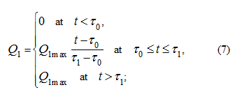
– the pump supply in node 1, Fig. 2. Considering dependences
Q
1
(
t
)
and
Then on the segment
Having accepted the initial conditions:
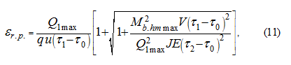
and considering (9), we solve system of the differential equations (6) which is linear at
where
u
– a transfer number of the turn mechanism.
Braking
where
р
* – the adjustment pressure of the pressure relief valve,
р
* = 4.9 MPa.
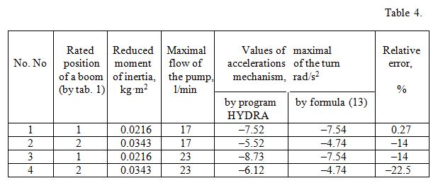
In tab. 4 results of calculation of maximal angular accelerations, received by means of program HYDRA and by means of the formula (13) are presented.
The received formulas provide the way approximately to define maximal angular accelerations of the turn mechanism. At performance of the conditions stipulated above in assumptions, the relative error has not exceeded 26% at dispersal and 23% at braking. The executed analysis has allowed carrying out in the further calculation on strength metallic structure of boom in view of dynamic loads. |
Contents
>> Analysis and Design
>> Systems of Hydraulic Drives
>> Hydraulic Drives of Auto Concrete Pumps
>> Dynamics of hydraulic drives of turn mechanism of the auto concrete pump BR-14
 we have: